


8
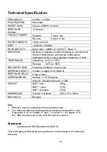
Technical description
A single switched antenna is used for both receive and transmit functions; the
switch normally connects the antenna to the receiver circuit. In the standby state
only the receiver portion of the SART is powered to reduce battery consumption to
a minimum. In this condition the indicator circuit causes the LED to flash once
every two seconds.
On receipt of a radar pulse the video amplifier and detector circuit causes the rest
of the circuitry to become active and the unit switches to transmit mode. In this
condition the indicator circuit causes the LED to remain steady and the buzzer to
sound every two seconds.
The detection of a radar pulse causes the switch to connect the antenna to the
transmitter circuit. The output stage is fed by a Voltage Controlled Oscillator (VCO),
whose frequency is determined by a sweep generator. When triggered by the
detector the sweep generator turns on the VCO and causes it to produce exactly 12
forward and reverse frequency sweeps before shutting down again.
If no radar pulses are detected for a period of 15 seconds the unit reverts to
standby mode.
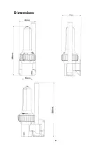
Function chart
SART STATUS
BUZZER
RED LED
OFF
OFF
OFF
STANDBY MODE
(TEST or ON)
OFF
FLASHING
EVERY 2 SECONDS
ACTIVELY
TRANSPONDING
(TEST or ON)
ON
EVERY 2 SECONDS
ON
Содержание S4 Rescue SART
Страница 1: ...S4 RESCUE SART Search And Rescue Transponder User Manual ...
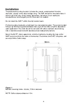
Страница 11: ...9 Dimensions ...
Страница 15: ...13 Declaration of Conformity ...
Страница 16: ...14 Declaration of Conformity page 2 ...
Страница 18: ...16 User Notes ...
Страница 19: ...17 This page contains no other data ...