TECHNICAL DESCRIPTION
FM SECTION:
The FM consists of two separate modu-
lar sections:
A THE RF SECTION:
This section houses the complete FM
front-end.
The FM circuit employs three junc-
tion field effect transistors, two of
which form the very high frequency
amplifier in a series-fed "cascode"
type circuit, giving maximum gain at
minimum thermal noise.
This VHF amplifier is preceded by a
double-tuned circuit and is followed
by a mixer circuit employing the third
junction field effect transistor and a
single-tuned circuit.
The FM local oscillator is designed
for minimum response to tempera-
ture variations, making automatic fre-
quency control unnecessary. The
drift rate is less than 10 parts per
megahertz per degree centigrade.
The RF circuits of the MX 114 are
completely shielded and exceed the
FCC requirements for suppression of
oscillator radiation.
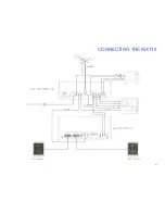
Either a 300 ohm or 75 ohm antenna
may be used with the MX 114.
A VHF television antenna which is
suitable for FM reception can be con-
nected to the MX 114. For maximum
performance we recommend a good
FM yagi or log-periodic antenna with
rotator.
B THE FM-IF AND DETECTOR
SECTION:
This section employs two integrated
circuit devices, each capable of am-
plifying the intermediate frequency
signal from the mixer by a thousand
times (60 db). Lumped selectivity in
the form of two sets of quadruple-
tuned bandpass filters insure good
intermediate frequency skirt selectiv-
ity.
The tuned circuits that make up the
bandpass filters are designed 1or
electrical stability and for electrical
and mechanical resistance to shock
and vibration.
"Hard" limiting is accomplished by
the use of the two integrated circuits.
The limiting is complete at very low
levels of input signals.
A phase or Foster-Seeley discrimi-
nator is used as the FM detector, and
is designed for extremely low har-
monic distortion in the recovered
output signal. With the "Hard" limit-
ing properties of the preceding two
stages a low capture ratio is obtained.
FM STEREO MULTIPLEX SECTION:
The multiplex section uses a special Mc-
lntosh developed detecting circuit. A par-
ticular advantage of this circuit is the
elimination of the critical adjustments
necessary with commonly used matrix-
ing circuits. This circuit detects the L —R
sidebands and automatically matrixes
the recovered information with the L + R
main carrier signal to yield the left and
right program output with maximum sep-
aration.
The 19KC pilot signal is filtered from the
composite stereo input signal, amplified
by a special limiting amplifier, doubled
to the 38KC carrier frequency, and then
amplified again by a limiting amplifier.
The composite signal minus the 19KC
pilot is combined with the 38KC carrier
signal and fed to the special detector cir-
cuit mentioned above. Balanced full wave
detectors are used to cancel the 38KC
components in the output.
A three section phase linear sharp cut off
filter rejects SCA interference without de-
stroying stereo separation.
FM muting, automatic FM stereo switch-
ing, and an FM stereo indicator are also
part of the multiplex section. The FM
muting operates by detecting ultra-sonic
noise which is present when tuning be-
tween stations or when receiving a weak
station. The FM muting operates equally
well, of course, when receiving mono or
stereo stations. The automatic FM stereo
switching activates the stereo multiplex
circuits when receiving FM stereo. On
mono FM stations this circuit is inactive
and therefore maximum signal to noise
ratio is assured at all times.
The FM stereo indicator is lit when the
tuning dial pointer crosses a station
broadcasting FM stereo. The light does
not indicate when tuning between the
stations.
3
Содержание MX 114
Страница 1: ...PREAMPLIFIER FM TUNER STEREO MX114 PRICE 1 25...
Страница 7: ...BLOCK DIAGRAM 6 PREAMPLIFIER SECTION TUNER SECTION POWER SUPPLY...
Страница 12: ...CONNECTING THE MX114 11...


