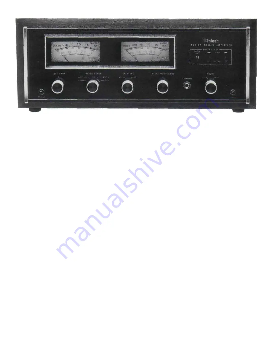
The Front Panel Controls and
How to Use Them
METERS
Output power monitor meters indicate the output
power of each channel. Each meter has two primary
scales: WATTS and DECIBELS. When the METER
RANGE switch is in one of the decibel (dB) posi-
tions, peak signal readings are indicated on the
lower DECIBEL scale. When the METER RANGE
switch is in the WATTS position, direct power in
watts is read from the upper watts scale. The meters
are calibrated to read average watts. The in-
termediate markings between the calibrations repre-
sent, beginning with 150 watts, 60 watts, 30 watts,
the indicated 15 watts, 6 watts, 3 watts, the in-
dicated 1.5 watts, 0.6 watt, 0.3 watt, the indicated
0.15 watt, 0.06 watt, 0.03 watt, the indicated 0.015
watt, 0.006 watt, 0.003 watt, the indicated 0.0015
watt, 0.0006 watt and 0.0003 watt. Although the
meter calibrations are in average watts for a sine
wave signal, the meters electrically respond to
signal peaks. The meters are voltage actuated and
indicate power accurately when the amplifier is
operated into rated output load impedances.
The meters respond to the peak output of each
channel. Ordinary meters lack the capability of in-
dicating the short interval information in a sound
wave. The mass of the meter movement is too great
to respond to the nearly instantaneous changes in
music program material. Short interval information
can have a duration as short as half a thousandth of
a second. Ordinarily, a meter pointer moving over its
scale in such a short time would not be seen.
Mclntosh has developed circuits that drive the
meters to respond to the short interval information
in a sound wave to an accuracy of 90%. The elec-
trical pulse that drives the meter pointer is time
stretched long enough so that the peak position of
the pointer can register in the persistence of vision
characteristic of the retina of the human eye.
LEFT GAIN
The LEFT GAIN control adjusts the volume in the
left channel to the desired listening level. Turn the
control clockwise to increase the volume.
RIGHT/MONO GAIN
The RIGHT/MONO GAIN control adjusts the
volume in the right channel to the desired listening
level. Turn the control clockwise to increase the
volume. When the output of MC 2155 is connected
for monophonic operation and the rear panel MODE
SWITCH is in the MONO position the volume is con-
trolled by the RIGHT/MONO GAIN control only.
METER RANGE
The METER RANGE switch has five positions.
9


