


The Choice: 1X, 2X, 4X AGP mode.
Delay Transaction:
The chipset has an embedded 32-bit posted write buffer to support delay
transactions cycles. Select
Enabled
to support compliance with PCI specification version 2.1.
The Choice: Enabled, Disabled.
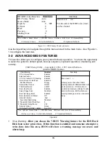
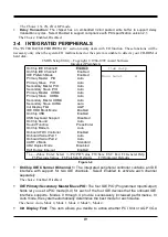
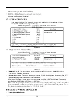
3-4 INTEGRATED PERIPHERALS
The “INTEGRATED PERIPHERALS” section mainly deals with I/O function. These functions will be
necessary only when the system I/O malfunctioned or the system is unable to detects your CD-ROM or
hard disk.
CMOS Setup Utility – Copyright © 1984-1999 Award Software
Integrated Preipherals
OnChip IDE Channel0 Enabled
OnChip IDE Channel1
Enabled
IDE Prefetch Mode
Enabled
Primary Master PIO Auto
Primary Slave PIO Auto
Secondary Master PIO
Auto
Secondary Slave PIO
Auto
Primary Master UDMA Auto
Primary Slave UDMA Auto
Secondary Master UDMA
Auto
Secondary Slave UdMA
Auto
Init Display First AGP
IDE HDD Block Mode Enabled
OnChip USB Enabled
USB Keyboard Support Disabled
OnChip Sound Auto
Sound Function Press Enter
OnChip Modem Auto
Onboard FDC Controller
Enabled
Onboard Serial Port 1 Auto
Onboard Serial Port 2 Auto
UART 2 Mode Standard
UR2 Duplex Mode Disabled
Half Duplex time-out
Enabled
Item Help
Menu Level
Move Enter: Select +/-/PU/PD: Value F10:Save ESC: Exit F1:General Help
F5:Previous Values F6:Fail-Safe Defaults F7:Optimized Defaults
Figure 3-4
OnChip IDE Channel 0/Channel 1:
The integrated peripheral controller contains an IDE
interface with support for two IDE channels. Select
Enabled
to activate each channel
separately.
The choice: Enabled, Disabled.
IDE Primary/Secondary Master/Slave PIO:
The four IDE PIO (Programmed Input/Output)
fields let you set a PIO mode (0-4) for each of the four IDE devices that the onboard IDE
interface supports. Modes 0 through 4
provide successively increased performance. In
Auto mode, the system automatically determines the best mode for each device.
The choice: Auto, Mode 0, Mode 1, Mode 2, Mode 3, Mode 4.
Init Display First:
This item allows you decide to active whether PCI Slot or AGP VGA
19