
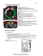


649-216
ETT Distribution GmbH Schmalbachstraße 16 38112 Braunschweig
Nachdruck oder Vervielfältigung nur mit ausdrücklicher Genehmigung
AC Voltage Measurement:
1.
Connect the red test lead with
V
Ω
mA
and the black one with
COM
.
2.
Turn the rotary switch to
V~
.
3.
Adjust the metering range. If you do not know the range in the first place choose the highest range
position and change it down until you can read a meaningful value on the display.
4.
Connect the heads of the test leads to the poles of the test object.
5.
Now the display shows the value of the.
Resolution: max. 100 mV
Accuracy: max. +/- (1.2% + 10 digits)
DC Current Measurement:
1.
Connect the red test lead with
V
Ω
mA
, or with
10A
if applicable, and the black one with
COM
.
2.
Turn the rotary switch to
A=
or to
10A
if applicable.
3.
Adjust the metering range. If you do not know the range in the first place choose the highest range
position and change it down until you can read a meaningful value on the display.
4.
Connect the heads of the test leads to the poles of the test object.
5.
Now the display shows the value of the current.
Resolution: max. 100 nA
Accuracy: max. +/- (2% + 2 digits)
Electric Resistance Measurement:
1.
Connect the red test lead with
V
Ω
mA
and the black one with
COM
.
2.
Turn the rotary switch to
Ω
.
3.
Adjust the metering range. If you do not know the range in the first place choose the highest range
position and change it down until you can read a meaningful value on the display.
4.
The object to be measured must be dead-voltage.
5.
Connect the heads of the sensors with the wire on either side of the component part which electric
resistance should be measured.
6.
Now the display shows the value of the electric resistance.
Resolution: max. 100 m
Ω
Accuracy: max. +/- (1.2% + 2 digits)
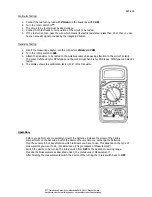
Diode Testing:
1.
Connect the red test lead with
V
Ω
mA
and the black one with
COM
.
2.
Turn the rotary switch to
.
3.
Connect the red sensor with the anode and the black one with the
cathode of the diode. These are marked by colors.
4.
The diode must be dead-voltage.
5.
Now the display shows the value of the forward bias through the diode.
6.
If the sensors are interchanged you can check the reverse-biasing of the
diode. This means thee should be no electricity at all and the display
should show 1.
Resolution: max. 1mV


