


McAfee® Network Security Platform 6.0
Troubleshooting Network Security Platform
23
1
Click
Options > Dashboard > New
to open the Create New Dashboard dialog.
2
Enter a name for the new dashboard in the
Dashboard Dialog
.
3
Click
Assign Monitor
to view the
Assign Monitor Dialog
.
4
Select the
Assign an existing Monitor
radio button.
5
Select
Default Monitors
against Category (these are the default choices).
6
Select
Sensor Performance
against Type to view the choice of Monitors for Sensor
Performance in the
Monitor
choices box.
7
Select
Statistics - Flows
and click
OK
.
8
Select the Sensor for which you wish to view flow statistics.
9
Click
Refresh
to view the flow statistics for the selected Sensor.
10
Follow a similar procedure and select other Monitors for Sensor Performance to view
the relevant Sensor Statistics.
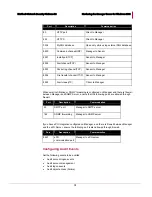
List of Monitors for Sensor Statistics
Sensor Flow Statistics: Statistical view of the TCP and UDP flow data processed by a
Network Security Sensor. Checking your flow rates can help you determine if your
Sensor is processing traffic normally, while also providing you with a view of statistics
such as the maximum number of flows supported as well as the number of active TCP
and UDP flows.
IP Spoofing Statistics: Statistics on the number of IP spoofing attacks detected by
McAfee Network Security Platform. Statistics are displayed per direction.
Packet Drop Statistics: Packet drop rate on a Sensor. The statistics is displayed on a
per Sensor basis. The statistics includes the count of number of packets dropped by
Sensor due to set rate limiting on the Sensor and sanity check failures.
Port Packet Drop Statistics: Packet drop rate on a port.
Rate Limiting Statistics: Rate limiting statistics provides the estimated number of
packets dropped/bytes dropped by the Network Security Sensor. You can view rate
limiting statistics for each Sensor (per port), listed in the resource tree of Manager
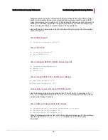
Checking Sensor failover status
To ensure that two Sensors comprising a failover pair are communicating via their
interconnection cable, go to each Sensor's CLI and type
show failover-status
.
Failover should display as enabled (YES), and the peer Sensor should display as UP.
Cabling failover through a network device
Do
not
cable the heartbeat connection through an external network device.
To keep overhead low and throughput high, the Sensors do not include layer 2 or 3
headers on the packets they pass over the heartbeat connection, and they pass data
larger than the standard Ethernet maximum frame size (1518 bytes).
If you attempt to place a network device, such as a switch or router, between the heartbeat
ports, the heartbeat connection will fail.


