background image

32

SECTION V

SERVICE/PARTS INFORMATION

A.  SERVICE

Only properly licensed or trained technicians should service the dryer.  If service is required, contact the dealer

from whom the equipment was purchased.  If the dealer 

cannot

 be contacted or is unknown, contact the

Maytag Co.

 for a dealer in your area.

NOTE:

When contacting the 

Maytag Co.

, be sure to give them the correct 

model number

 and

serial number

 so that your inquiry is handled in an expeditious manner.

B.  PARTS

Replacement parts 

should be

 purchased from the dealer from whom the 

Maytag

 equipment was purchased.  If

the dealer 

cannot

 be contacted or is unknown, contact the 

Maytag Co.

 for a dealer in your area.

NOTE:

When ordering replacement parts from the 

Maytag Co.

, be sure to give them the correct

model number

 and 

serial number

 so that your parts order can be processed in an

expeditious manner.

Содержание MLG31PCB

Страница 1: ... Installation and service must be performed by a qualified installer service agency or the gas supplier AVERTISSEMENT Assurez vous de bien suivrelesinstructionsdonnéesdanscettenotice pour réduire au minimum le risque d incendie ou d explosion ou pour éviter tout dommage matériel toute blessure ou la mort Ne pas entreposer ni utiliser d essence ni d autres vapeurs ou liquides inflammables à proximi...

Страница 2: ...les àproximitédecet appareil ou de tout autre appareil We have tried to make this manual as complete as possible and hope you will find it useful The manufacturer reserves the right to make changes from time to time without notice or obligation in prices specifications colors and material and to change or discontinue models The illustrations included in this manual may not depict your particular d...

Страница 3: ...IFNEARDRYERSINOPERATION CAUTION DRYERSSHOULDNEVERBELEFTUNATTENDEDWHILEINOPERATION FORYOUR SAFETY DONOTDRYMOPHEADSINTHEDRYER DONOTUSEDRYERINTHEPRESENCEOFDRYCLEANINGFUMES WARNING UNDER NO CIRCUMSTANCES should the dryer door switch lint drawer switch or heat safety circuit ever be disabled Caution Label all wires prior to disconnection when servicing controls Wiring errors can cause improper operatio...

Страница 4: ...ncluded with the dryer WARNING DRYER MUST NEVER BE OPERATEDWITHOUTTHE LINTFILTER SCREEN IN PLACE EVENIFANEXTERNALLINTCOLLECTIONSYSTEMISUSED Dryer must not be installed or stored in an area where it will be exposed to water or weather The wiring diagram for the dryer is located in the front electrical control box area IMPORTANT Dryer must be installed in a location environment which the ambient tem...

Страница 5: ...ments 11 F ElectricalInformation 18 G GasInformation 20 H Preparation For Operation 25 I PreoperationalTests 25 J ShutdownInstructions 28 SECTION IV OPERATING INSTRUCTIONS 29 A Coin Mode 29 B Free Mode 30 C Pause Mode 30 D RPM 30 E ClearingCredit ClearingCycle 31 F AccessingCoinVault 31 G WrinkleGuard 31 SECTION V SERVICE PARTS INFORMATION 32 A Service 32 B Parts 32 SECTION VI WARRANTY INFORMATION...

Страница 6: ...SECTION VII ROUTINE MAINTENANCE 34 A Cleaning 34 B Adjustments 35 C Lubrication 35 SECTION VIII DATA LABEL INFORMATION 36 SECTION IX PROCEDURE FOR FUNCTIONAL CHECK OF REPLACEMENT COMPONENTS 38 ...

Страница 7: ... c DO NOT use any phone in your building d Clear the room building or area of ALL occupants e Immediately call your gas supplier from a neighbor s phone Follow the gas supplier s instructions f If you cannot reach your gas supplier call the fire department 4 Installation and service must be performed by a qualified installer service agency or gas supplier 5 Dryer s must be exhausted to the outdoor...

Страница 8: ...switch lint drawer switch or heat safety circuit ever be disabled WARNING PERSONALINJURYOR FIRE COULD RESULT should the dryer door switch lint drawer switch or heat safety circuit ever be disabled 10 This dryer is not to be used in the presence of dry cleaning solvents or fumes 11 Remove articles from the dryer as soon as the drying cycle has been completed WARNING Articles left in the dryer after...

Страница 9: ... 7 780 5 02725 3 6 KS N 225 23 1 1 0 7 5 3 6 FP 92 7 9 Y Z 3352 7 81 5 7 OEV NJ 3352 7 5 7 OEV NJ 7 1387 727 25 27 6 76 WX KU NFDO KU 5 2 3 5 6 7 780 5 FIP FPP 6 1 7 6 3 6 1 3 7 Shaded areas are stated in metric equivalents 1 15 04 NOTE Manufacturerreservestherighttomakechangesinspecificationsatanytimewithoutnoticeor obligation ...

Страница 10: ...6 NOTE Manufacturerreservestherighttomakechangesinspecificationsatanytimewithoutnoticeor obligation SPECIFICATIONS GAS ONLY ...

Страница 11: ...where or the lock can be ordered as a parts order from the manufacturer The dryer can be moved to its final location while still attached to the skid or with the skid removed To unskid the dryer locate and remove the four 4 bolts securing the base of the dryer to the wooden skid Two 2 are at the rear of the base and two 2 are located in the front Once the bolts are removed slide the dryer off the ...

Страница 12: ...is manual refer to Dryer Enclosure Requirements in Section C Even though a 12 inch 30 48 cm clearance is acceptable it is recommended that the rear of the dryer be positioned approximately 2 feet 0 61 meters away from the nearest obstruction i e wall for ease of installation maintenance and service Refer to the illustration below 6 Provisions must be made for adequate clearances for servicing and ...

Страница 13: ...enance and service above the dryer s outer top except along the front of the dryer which may be closed in if desired NOTE Even though a minimum of 12 inches 30 48 cm above the dryer s outer top is acceptable a clearance of 18 inches 45 72 cm or more is suggested for ease of installation and service electricalpowerconnections NOTE When fire sprinkler systems are located above the dryers a minimum o...

Страница 14: ...f 12 square feet 1 15 square meters is required Two 2 openings measuring 2 feet by 3 feet 0 61 meters by 0 91 meters 6 square feet 0 56 square meters are acceptable The dryer must be installed with provisions for adequate combustion and make up air supply Allowances must be made for remote or constricting passageways or where dryers are located at excessive altitudes or predominantly low pressure ...

Страница 15: ...the weather no more than two 2 elbows should be used in the exhaust duct run If more than two 2 elbows are used the cross section area of the ductwork must be increased in proportion to the number of elbows added 1 Exhaust Connections of Top and Bottom Baskets Tumblers There is no common venting connection provided with the dryer Each basket tumbler exhaust duct is provided with its own back draft...

Страница 16: ...ng HVAC firm shouldbe consulted for proper venting information The ductwork should be smooth inside with no projections from sheet metal screws or other obstructions which will collect lint When adding ducts the duct to be added should overlap the duct to which it is to be connected ALL ductwork joints must be taped to prevent moisture and lint from escaping into the building Also inspection doors...

Страница 17: ...13 ...

Страница 18: ...14 ...

Страница 19: ... square or rectangular duct must be increased twenty percent 20 for each additional 15 feet 4 57 meters The diameter of a round exhaust must be increased ten percent 10 for each additional 15 feet 4 57 meters IMPORTANT For extended ductwork runs the cross sectional area of the ductwork can only be increased to an extent Maximum proportional ductwork run cannot exceed 15 feet 4 57 meters more than ...

Страница 20: ... up through the roof it should be protected from the weather by using a 180º turn to point the opening downward In either case allow at least twice the diameter of the duct between the duct opening and nearest obstruction IMPORTANT DO NOT use screens louvers or caps on the outside opening of the exhaust ductwork NOTE Refer to the illustrations onpage 17 for examples of multiple dryer common ventin...

Страница 21: ...17 ...

Страница 22: ...Y It is recommended that a separate circuit servicing each basket tumbler be provided The dryer must be connected to copper wire ONLY DO NOT use aluminum wire which could cause a fire hazard NOTE TheuseofaluminumwirewillVOIDTHEWARRANTY 2 Electrical Connections A wiring diagram is included with each dryer showing the wiring connection sequence The electrical connections are made in a box located at...

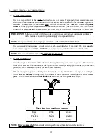
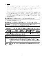
Страница 23: ...plastic rubber or other insulating connectors they must be jumped out with No 4 wire and securely clamped to bare metal at both ends IMPORTANT For personal safety and proper operation the dryer must be grounded 4 Electrical Service Specifications per pocket IMPORTANT The dryer must be connected to the electrical supply shown on the data label WARNING Any damage done to dryer components due to impr...

Страница 24: ...e or disconnect the dryer from supply as noted could cause irreparable damage to the gas valve which willVOIDTHEWARRANTY WARNING FIRE OR EXPLOSION COULD RESULT due to failure of isolating or disconnecting the gas supply as noted 1 Gas Supply The gas dryer installation must meet the American National Standard National Fuel Gas Code ANSI Z223 1 LATESTEDITION or in Canada the Canadian Installation Co...

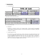
Страница 25: ...use with L P gas have the gas valve s internal pressure regulator blocked open so that the gas pressure must be regulated upstream of the dryer The pressure measured at each gas valve pressure tap must be a consistent 10 5 inches 26 1 mb water column There is no regulator or regulation provided in an L P dryer The water column pressure must be regulated at the source L P tank or an external regula...

Страница 26: ...provided with two 2 1 2 N P T inlet pipe connections one 1 for each basket tumbler at the rear of the dryer If a separate feed is provided for each basket tumbler from the main supply line header then a 1 2 12 7 mm line connection is sufficient However if the top and bottom basket tumbler connections are connected together the supply from the header must be increased to 3 4 inch 19 05 mm An option...

Страница 27: ...the bank of dryers An in line pressure regulator must be installed in the gas supply line header if natural gas line pressure exceeds 12 0 inches 29 9 mb water column W C pressure Refer to the illustration on page 24 for details IMPORTANT Water column pressure of 3 5 inches 8 7 mb for natural gas dryers and 10 5 inches 26 1 mb for L P gas is required at the gas valve pressure tap of each dryer for...

Страница 28: ...24 ...

Страница 29: ...ck the lint door to ensure that it is closed and secured in place 9 Rotate the basket tumbler by hand to be sure they move freely 10 To facilitte door closure and better tumbling action and improved efficiency the dryer should be tilted slightly to the rear I PREOPERATIONAL TESTS ALL dryers are thoroughly tested and inspected before leaving the factory However a preoperational test should be perfo...

Страница 30: ...opriate temperature selection key 4 Upon completion of the drying and cooling cycles the buzzer will sound and the dryer will go into the Anti Wrinkle mode for 99 minutes or until the main door is opened IMPORTANT For complete operation details for the computer system refer to the user s manual includedwiththedryer 3 Heat Circuit Operational Test Gas Models When a gas dryer is first started during...

Страница 31: ...d for proper operation by opening the control door while the dryerisrunningandtheheatingunit burner isactive on Theheatingunitshouldshutoff within a few seconds If not make the necessary adjustments BASKET TUMBLER COATING The basket tumbler is treated with a protective coating We suggest dampening old garments or cloth material with a solution of water and nonflammable mild detergent and tumbling ...

Страница 32: ...her at the external disconnect switch or the circuit breaker 2 Discontinue the gas supply a SHUT OFF external gas supply shutoff valve for both the top basket tumbler and the bottom basket tumbler where the independent supply line for each basket tumbler is used b SHUT OFF internal gas supply shutoff valve located in the gas valve burner area for both the top basket tumbler and the bottom basket t...

Страница 33: ...es until the vended time has expired 5 Upon completion of drying and cooling cycles the buzzer will sound and the dryer will go into Wrinkle Guard mode for 99 minutes or until the door has been opened 6 HOT KEYS When the control is in coin mode the HOT KEYS are disabled The HOT KEYS can be enabled only if the dryer is in a dry cycle The HOT KEYS cannot be enabled if the dryer is in READY INSERT 25...

Страница 34: ...al temperature transducer will also be displayed this will be the middle temperature reading Pressing and holding the LO key will show the RPMs of the basket tumbler The PAUSE key will pause the dryer If the dryer is paused pressing the HI MED or LO key will restart the dryer into the appropriate drying cycle Once the dry cycle has started again the HOT KEYS will be enabled again C PAUSE MODE If t...

Страница 35: ...is in the UP position press the HI key The controller will now display the amount of money in the coin vault Press the HI key again and the controller will ask to CLEAR COIN VAULT TOTAL Press PAUSE for NO and press MED for YES G WRINKLE GUARD This program keeps items wrinkle free when they are not removed from the dryer promptly at the end of the drying cycle and or cooling cycle When the drying a...

Страница 36: ...ng the Maytag Co be sure to give them the correct model number and serialnumber sothatyourinquiryishandledinanexpeditiousmanner B PARTS Replacement parts should be purchased from the dealer from whom the Maytag equipment was purchased If the dealer cannot be contacted or is unknown contact the Maytag Co for a dealer in your area NOTE When ordering replacement parts from the Maytag Co be sure to gi...

Страница 37: ...ned for each individual dryer NOTE Besuretoincludetheinstallationdatewhenreturningwarrantycard s B WARRANTY For a copy of the manufacturer s commercial warranty covering your particular dryer s contact the dealer from whom you purchased the equipment and request a dryer warranty form If the dealer cannot be contacted or is unknown warranty information can be obtained from the Maytag Co NOTE Whenev...

Страница 38: ... HAZARD WARNING KEEPDRYERAREACLEARAND FREE FROM COMBUSTIBLE MATERIALS GASOLINE AND OTHER FLAMMABLE VAPORSAND LIQUIDS NOTE Suggested time intervals shown are for average usage which is considered six 6 to eight 8 operational running hoursperday IMPORTANT Dryer produces combustible lint and must be exhausted to the outdoors Every 6 months inspecttheexhaustductingandremoveanylintbuildup SUGGESTED CLE...

Страница 39: ...alves and orifices Motor and drive belts should be examined Cracked or seriously frayed belt s should be replaced Tighten loose belt s when necessary Complete operational check of controls and valves Complete operational check of ALL safety devices door switches lint drawer switch sail switch burner and hi limit thermostats C LUBRICATION The motor bearings idler bearings and under normal most cond...

Страница 40: ...ormation is required to ensure proper service parts information This information is on the data label which is located in the gas train area right inside wall near sail switch behind the middle control access door When contacting the Maytag Co please have the model number and serial number available ...

Страница 41: ... describes ALL possible options on your particular model 4 TYPE OF HEAT This describes the type of heat for your particular dryer gas either natural gas or liquid propane L P gas electric or steam 5 HEAT INPUT for GAS DRYERS This describes the heat input in British Thermal Units per Hour Btu hr 6 ORIFICE SIZE for GAS DRYERS Gives the number drill size used 7 ELECTRIC SERVICE This describes the ele...

Страница 42: ...PLACEMENT COMPONENTS KEYBOARD TOUCH PAD LAYOUT 1 Liquid Crystal Display 2 Top Pocket HI key 3 Top Pocket MED Key 4 Top Pocket LO Key 5 Top Pocket PAUSE Key 6 Bottom Pocket HI Key 7 Bottom Pocket MED Key 8 Bottom Pocket LO Key 9 Bottom Pocket PAUSE Key ...

Страница 43: ...ation No L E D indicator indicates a power or an internal failure has occurred 2 For Models with Fenwal Controls DSI Module 128937 Theory of Operation Start the drying cycle When the gas burner ignites within the chosen trial for ignition time 8 seconds the flame sensor detects gas burner flame and signals the DSI module to keep the gas valve open as long as there is a call for heat The DSI module...

Страница 44: ...ng Kit P N880128 ITEM QTY P N DESCRIPTION 1 1 143600 10 X 6 X 6 Y DUCT 2 1 143519 FLEX DUCT 6 x 4 LONG 3 1 143509 FLEX DUCT 6 x 8 LONG 4 2 143536 45º ELBOW 6 NOT ILLUSTRATED 12 150300 10 x 1 2 SELF DRILLING SCREW NOT ILLUSTRATED 12 117505 ALUMINUM DUCT TAPE ...

Страница 45: ...Part Number 113203 2 1 15 04 100 ...

Отзывы: