


Installation and Operational Instructions for
ROBATIC
®
-clutch Type 500.1_ _ and Type 580.1_ _
Sizes 3 – 9
(B.5.0.GB)
28/08/2007 TK/RB/RJ
Chr. Mayr GmbH + Co. KG
Tel.: 08341 / 804-241
Eichenstraße 1
Fax: 08341 / 804-422
87665 Mauerstetten
http://www.mayr.de
Page 6 of 8
Germany
eMail:
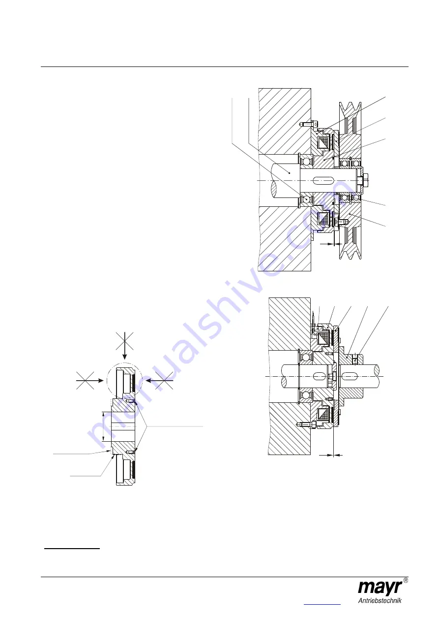
Installation Example 1 (Fig. 3)
Please Observe: Positions 8 to 11 are customer-side-mounting
components which are not included in delivery.
In operation, the armature disk (4) is pulled against the rotor (3).
The torque is transmitted via frictional locking from the drive shaft
(9) via the rotor (3) and the armature disk (4) onto the
V-belt disk (8).
The coil carrier (1/2) is screwed onto the machine wall, centred onto
the shaft bearing (10).
The air gap "a" between the rotor (3) and the armature disk (4) is
defined via the distance ring (11) between the rotor (3) and the V-
belt disk (8) bearing.
The V-belt disk (8) should be made from a material which is a poor
magnetic conductor in order to prevent magnetic loss due to leaking
flux and therefore loss of force. IN VOC it says: leakage flux
Installation Example 2 (Fig. 4)
Electromagnetic clutch with flange hub (7) for the connection of two
aligning shafts.
Torque Procedure:
Input shaft – rotor (3) – armature disk (4) – flange hub (7) – output
shaft.
The coil carrier (1/2) and the rotor (3) are mounted input-side, the
flange hub (7) with the screwed-on armature disk (4) is mounted
onto the output shaft.
Axial securement of the rotor (3) takes place via a press cover and
a screw, screwed into the central shaft thread. A set screw (7.1)
secures the flange hub (7) onto the output shaft. For adjustment of
air gap "a" between the rotor (3) and the armature disk (4), the set
screw is loosened and the flange hub (7) is moved onto the output
shaft.
Boring the rotor hub (Fig. 2)
Fig. 2
The rotor (3) must not be bent during boring.
Do not place pressure on the outer, thin-walled rotor area,
see Fig. 2.
To bore, clamp on the rotor hub.
The maximum permitted bore diameter d
max.
, acc. Table 1, must not
be exceeded. The keyway is produced acc. DIN 6885/1.
Exception for size 4: Here, the keyway is produced up to Ø 23
keyway acc. DIN 6885/1 and over Ø 23 keyway acc. DIN 6885/3.
We recommend H7/k6 as a suitable hub-shaft tolerance.
Fig. 3
Fig. 4
a
10
9
1
4
11
3
8
1
3
4
7
7.1
a
Ø
d
m
a
x
Do not place
pressure here
Bore intake
Turn-on for
ball bearing
Tapped extracting hole


