


Installation and Operational Instructions for
ROBA
®
-ES Couplings Type 94_._ _ _._ Sizes 14
– 65
(B.9.6.EN)
11/03/2022 TK/GH/GC/MD
Chr. Mayr GmbH + Co. KG
Eichenstraße 1, D-87665 Mauerstetten, Germany
Phone: +49 8341 804-0, Fax: +49 8341 804-421
Page 21 of 29
Balancing the Coupling
Clamping hubs (0/5), key hubs (2), split clamping hubs (3)
and expansion hubs (4)
rotate at maximum speed with a
circumferential speed of 30 m/s.
They are not balanced for standard delivery.
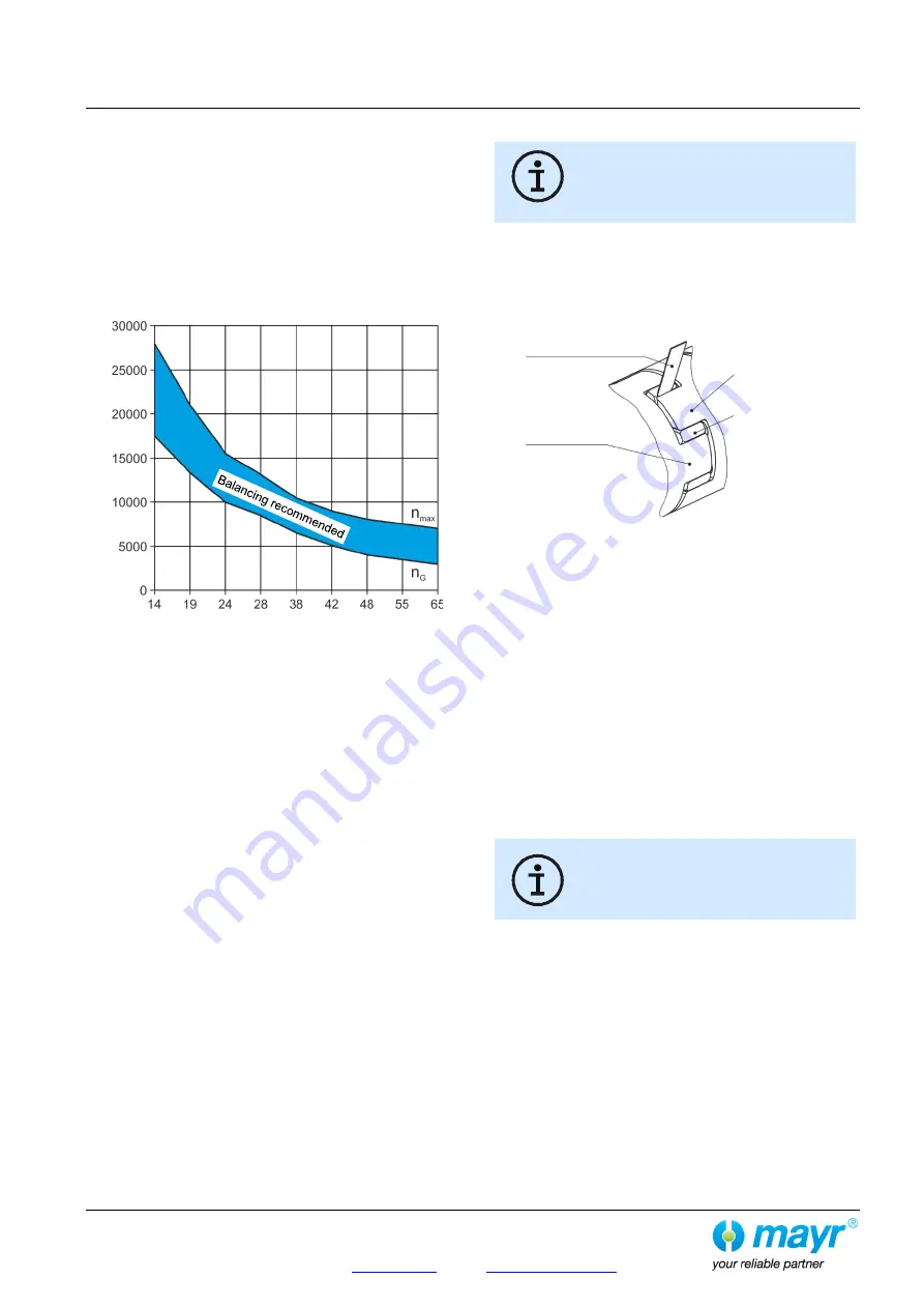
Shrink disk hubs (1) made of steel and aluminum
maintain
balance quality G = 6.3 up to speed n
G
(equals approx. 20
m/s) without needing to be balanced. Above this speed, we
recommend balancing. The hubs are balanced individually.
The diagram (Fig. 19) shows reference values. We
recommend you use these values to balance the coupling
components.
Fig. 19
(Balancing the shrink disk hubs)
Smooth running of the machine is not only ensured by the
coupling balance quality, but is also influenced by parameters
such as rigidity and distance to the adjacent bearings as well as
by the sensitivity and mass of the entire construction.
Figure 19, therefore, only shows reference values as
recommendations for balancing.
Maintenance
The following maintenance and inspection intervals are to be
maintained:
1.) Visual inspection. Inspection of the installation parameters
(misalignment and tightening torques) and the coupling
running behavior
before initial operation.
2.) Check the tightening torques produced
after 5 to 10 operating hours.
3.) Visual inspection, torsional backlash and elastomer wear,
inspection of the misalignment and the tightening torques,
coupling running behavior
after 1000 h, at the latest after 3 months.
4.) If no irregularities or wear are found during the maintenance
and inspection interval defined in point 3.), further inspection
intervals can, with unchanged operating parameters, take
place
after 4000 operating hours or after maximum 12
months.
5.) Replacement of the elastomeric element
after 5 years.
In extreme coupling ambient or operating conditions, the
maintenance and inspection intervals should be shortened.
Elastomer wear limit:
Elastomeric elements are parts subject to wear,
which change their characteristics depending
on the ambient conditions and loads.
The maximum operating time for the elastomer
is 5 years.
No abraded particles are allowed on the elastomeric element (6),
as the ROBA
®
-ES is a backlash-free coupling. The gap between
two claws must be filled with the elastomer, with no room for
backlash.
You should not be able to insert a feeler gauge with a thickness of
0.1 mm
(Fig. 20).
Fig. 20
If wear or damages are detected, the affected components must
be replaced immediately and the cause of the malfunction must
be determined.
Causes of malfunctions could be:
a) Excessive misalignment
b) Excessive load (load alternations, start-up impacts, overload)
c) Ambient influences
Wear or damage on the ROBA
®
-ES coupling manifest themselves
as:
a) Noise development
b) Troubled running behavior, vibration occurrences
c) Formation of cracks on the components
d) Warming
e) Loosening of the components
f) Friction tracks
Should any irregularities occur, the system
must be stopped independently of imminent
maintenance and inspection intervals, and the
cause of the malfunction must be determined
using the Malfunctions / Breakdowns Table.
Disposal
All steel components:
Steel scrap
(Code No. 160117)
All aluminum components:
Non-ferrous metals (Code No. 160118)
Elastomer:
Plastic
(Code No. 160119)
Size
Spe
e
d
rpm
Feeler gauge
0.1 mm
Hub 1
Hub 2
Elastomeric
element