


Installation and Operating Instructions for
EAS
®
-Sm/Zr Switch Gear
Type 010.000.2
(B.0100002.GB)
Page 1 of 6
10/03/2005 CB/KR/TH
Chr. Mayr GmbH + Co. KG Telephone 08341/804-241
Eichenstraße 1
Fax 08341/804-422
D-87665 Mauerstetten
http://www.mayr.de
Germany
eMail: [email protected]
Antriebstechnik
Manufacturer’s declaration
The product is a component in compliance
with the machine guideline 98/37/EC
which is determined for an installation into
a machine or equipment.
An initial start-up is prohibited until it has
been noticed that the machinery or the
equipment into which this product shall be
incorporated, corresponds to the EC-
guidelines.
The product corresponds to the low-
voltage directives 73/23/EEC.
The product corresponds to the EMC-
guideline 89/336/EEC.
Safety regulations
Attention!
Only qualified and well-trained specialists may work on the units under
observance of the valid standards and guidelines to avoid any personal injury
or damages to components. The installation and operating instructions must
be read carefully.
•
Hazardous conditions when contacting hot connections and / or
components.
•
Switch-off the input voltage before opening the unit and wait for
15 minutes.
•
Electronic units are cardinally not fail-safe.
•
Only work in a de-energized condition and secure it against unintended
reconnection.
Note:
Based on the guideline 94/9/EC (ATEX-guideline) this product is not suitable
for the application in potential explosive areas without evaluation of the
conformity.
Application
Switching, controlling, monitoring and overload signalling of
adjustable EAS
®
-Sm synchronous-clutches, EAS
®
-Zr overload
clutches.
Function
The EAS
®
-Sm/Zr-control unit works according to the cycled
switching controller principle with a frequency of 18 kHz.
It switches, controls and monitors the clutch and signals when the
set torque is exceeded.
Switching with
•
potential free contacts
•
PLC-drive with 10–30 VDC
Controlling by
•
coil current
Monitoring with
•
magnetic field resistant
proximity switches up to
+100 °C (potential free
contacts)
Temperature
monitoring
•
coil-clutch >+130 °C
•
control unit
>
+80 °C
Electrical connections
PE, L1, N
Connection input voltage
Ku1 / Ku2
Coil connection for clutch
14 – 11 – 12
Contact signalling relay 1 (overload)
24 – 21 – 22
Contact signalling relay 2 (over
temperature)
ON
Connection „Start“ button
OFF
Connection „Stop“ button
Gnd1
(-) Connection with PLC-drive
End
Limit switch signal
Gnd2
(-) Connection for limit switch
12V
(+) Connection for ON-button, OFF-
button and limit switch
Gnd3
(-) Connection with analogue
torque adjustment
M
(+) Connection with analogue
torque adjustment
P1,P2
Connection of the coil posistor
(or bridge)
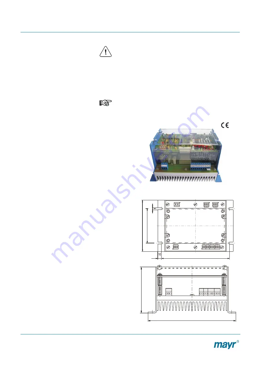
Dimensions (mm)
Clutch
Signalling relay
2
1
Mains
Control inputs
182
9
5
1
5
0
5
202
1
0
3


