


Installation and Operational Instructions for
EAS
®
-HTL housed overload clutch, Type 4190._5400
Sizes 4 and 5
(B.4.15.8.EN)
14/04/2020 TK/GH/MD/SU
Chr. Mayr GmbH + Co. KG
Eichenstraße 1, D-87665 Mauerstetten, Germany
Phone: +49 8341 804-0, Fax: +49 8341 804-421
Page 7 of 12
Installation Preparations (Customer-side)
Bore and shaft surface quality:
Ra = 1.6 µm acc. DIN 4287.
Shaft material: Yield point at least 400 N/mm
2
,
e. g. St 60, St 70, C 45, C 60.
Bore tolerance:
F7
Shaft tolerance:
k6.
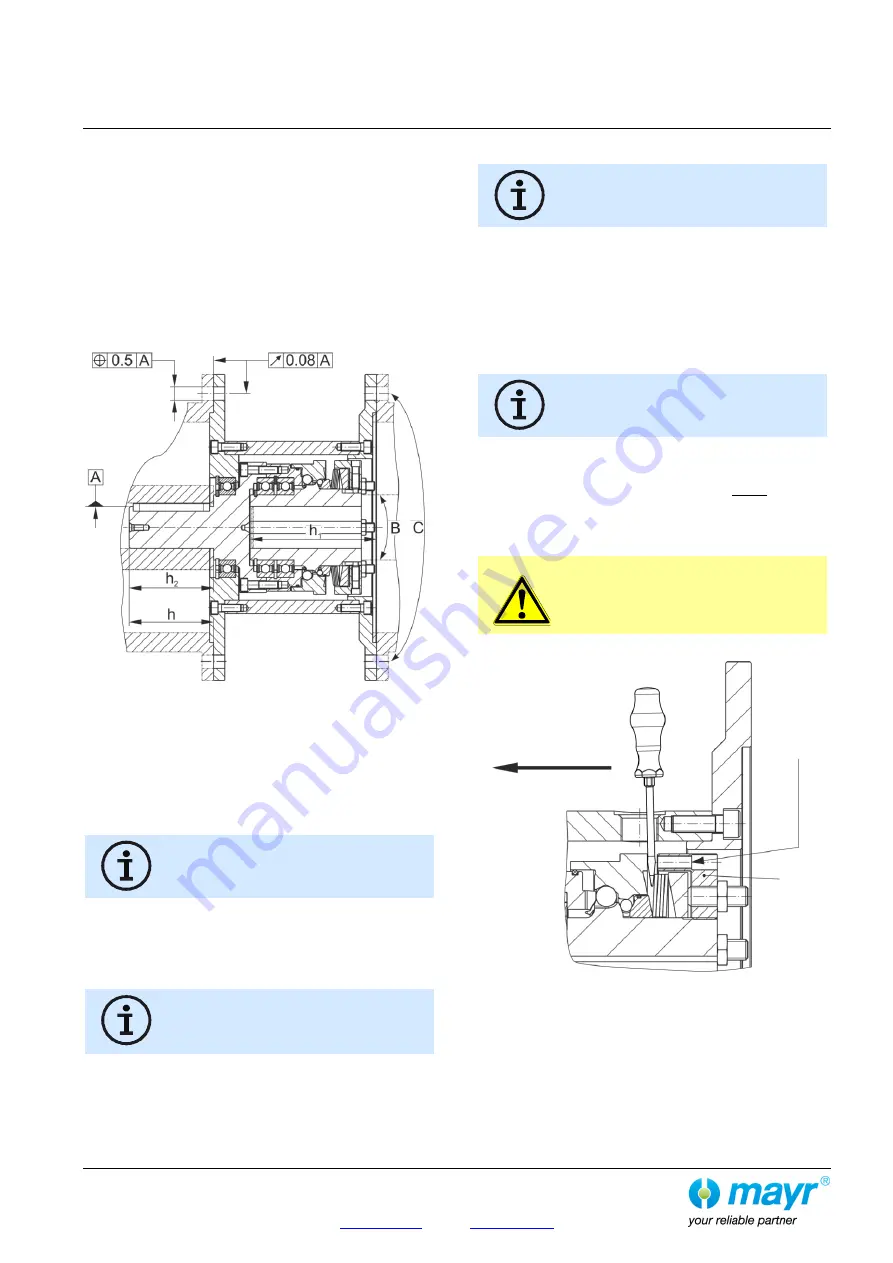
Shape and position tolerances (flange geometry):
Manufactured for clutch transmission part acc. Fig. 3.
Fig. 3
Installation (Figs. 1 to 3)
Join the manufacturer-assembled and adjusted clutch on the
output side, turn it to the correct position (flange bores must
align with the fixing threads) and bolt it together with the
mounting part (flange “Y”).
Please observe the attachment specifications indicated in
Tables 4 and 5.
Please observe clutch dimensions h and h
2
(see Table 3 and Fig. 3).
Insert flange “Z” with the shaft into the clutch hub bore (Item
1.1) or in the flange inner centring (Item 4), turn it to the
correct position (flange bores must align with the fixing holes)
and bolt it together with the mounting part (flange “Z”).
Please observe the attachment specifications indicated in
Tables 4 and 5.
Please observe the dimension h
1
(see Table 3
and Fig. 3).
The maximum permitted shaft length is:
h
1
-2 mm.
Re-engagement (Fig. 4)
Re-engagement must only take place when the
device is not running.
There are two bores (180° offset to one another) for manual
clutch re-engagement. They are locked with screw plugs (12).
In order to re-engage the clutch, at least one of the two screw
plugs (12), including its O-ring (13), must be loosened and
removed.
EAS
®
-Compact
®
overload clutch re-engagement is carried out by
applying axial pressure to the thrust washer (1.3) in the direction
of the output (flange Y) using a suitable lever tool (Fig. 4).
It may
be necessary to turn slightly between the
pressure flange (1.2)
and the thrust washer
(1.3)
.
Please make sure that the bore threads (for
screw plugs Item 12) in the distance ring (5)
are not damaged by the lever tool.
In the very high and maximum torque ranges (Types 4190.75400
and 4190.85400), engagement using a lever tool is no longer
easily possible.
Alternatively, re-engagement can take place by evenly screwing
three screws M8 (not included in the standard scope of delivery)
into the adjusting nut (Item 1.4 / Fig. 4).
On this variant, it may be
necessary to turn slightly between the
pressure flange (1.2)
and
the thrust washer
(1.3)
.
CAUTION
After re-engagement has taken place, the three
screws must be removed immediately, as they
could stop the clutch functioning (blockage).
Fig. 4
After re-engagement has been completed successfully, the
access bore must be re-closed using the screw plug (12) and
the O-ring (13) placed under it.
Flange “Y”
Output
Flange “Z”
Input
Re-engagement
direction
T
hread
for
re
-en
ga
ge
m
en
t