Mayr EAS-HT 405 Series Скачать руководство пользователя страница 9

Installation and Operational Instructions for


EAS

®

-HT clutch  Type 405_._ _400


Sizes 7 

– 10


(B.4050.1.EN)


16/04/2019 TK/GH/SU


Chr. Mayr GmbH + Co. KG


Eichenstraße 1, D-87665 Mauerstetten, Germany


Tel.: +49 8341 804-0, Fax: +49 8341 804-421


Page 9 of 9 

www.mayr.com

E-Mail

[email protected]


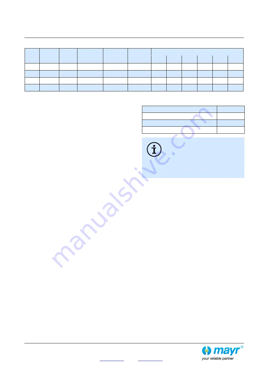
Table 3: Technical Data and Screw Tightening Torques 

Size


Air gap 


a

1


[mm]


Dimension


p


[mm]


Bolt 


pre-tension


[mm]


Max. 


radial forces


[kN]


Max. 


axial forces


[kN]


Screw tightening torques [Nm]


Item 6 

Item 8 

Item 16  Item 20  Item 24  Item Z 

8.0 

0.5 

+0.2


22.5 

16 

44 

160 

160 

32 

8.0 

0.5 

+0.2


30 

21 

76 

240 

240 

32 

8.0 

0.5 

+0.2


45 

31.5 

182 

240 

240 

32 

10 

10.5 

0.6 

+0.2


60 

42 

182 

19 

490 

490 

63 


Maintenance and Maintenance Intervals 

  Re-greasing of the overload elements (2), the bearing, the 

thrust pieces (4) and the ball bearing track via the cone 
lubricating nipples (Items 11, 12 and 13 / Fig. 3) at least 
every 20 overload occurrences or 1x per year, see Table 4. 

  Maintenance work, which should be carried out after approx. 

2000 operating hours, after 100 disengagements or at the 
latest after 1 year, includes: 

  Visual inspection 

  Functional inspection 

  Inspection of the shaft-hub connection 

  Inspection of the screw tightening torques 

The specified tightening torques (see table 3) must be 
maintained. 

  Inspection of the set torque 

  Clutch release inspection 

  Inspection of the bearing or bearing pre-tension 

  Re-greasing of the overload elements (2) via the cone 

lubricating nipples (11) on each overload element (2), 
see Fig. 3. 

  Re-greasing of the bearings via the cone lubricating 

nipples (Item 12 / Fig. 3) in the pressure flange (3),  
2 x 180° offset. 

  Re-greasing of the thrust pieces (4) and the ball bearing 

track via the cone lubricating nipples (Item 13 / Fig. 3) in 
the pressure flange (3), 2 x 180° offset.  

Clutch re-greasing must only be carried out by specially 
trained personnel. 


For greasing, please use NLGI Class 1.5 grease with a basic oil 
viscosity of 460 mm

2

/s at 40 °C, e.g. Mobilith SHC460. 

When re-installing the clutch, please secure all screws with  
Loctite 243 (medium hard). 

If large amounts of dirt or dust are present or in extreme ambient 
conditions, it may well be necessary to carry out inspections at 
shorter intervals. 

We recommend that maintenance work is carried out at the 
site of manufacture. 


Table 4: Greasing 

Lubrication points 

Quantity 

Item 11 

2 ccm 

Item 12 

8 ccm 

Item 13 

10 ccm 


On balanced clutches, please observe: 

Maintaining the exact angular position between 
the clutch components is absolutely necessary 
for maintaining the balance quality. 
On balanced clutches, the components are 
therefore marked and are, on re-installation, to 
be screwed together again in the 

marked 

angular position 

to the tightening torque 

according to Table 3. 


Disposal 

Electronic components


(Limit switch): 
Products which have not been disassembled can be disposed of 
under Code No. 160214 (mixed materials) or components under 
Code No. 160216, or can be disposed of by a certified disposal 
firm. 

All steel components:


Steel scrap  

(Code No. 160117) 

Seals, O-rings, V-seals, elastomers:


Plastic  


(Code No. 160119) 

Содержание EAS-HT 405 Series

Страница 1: ...ion and Operational Instructions I O are part of the clutch delivery Please keep them handy and near to the clutch at all times It is forbidden to start initial operation of the product until you have ensured that all applicable EU directives and directives for the machine or system into which the product has been installed have been fulfilled At the time these Installation and Operational Instruc...

Страница 2: ...Sizes 7 10 B 4050 1 EN 16 04 2019 TK GH SU Chr Mayr GmbH Co KG Eichenstraße 1 D 87665 Mauerstetten Germany Tel 49 8341 804 0 Fax 49 8341 804 421 Page 2 of 9 www mayr com E Mail info mayr com Fig 1a switching disk option Fig 1 Type 4050 _ _400 Fig 2 Type 4053 _ _400 Stroke Stroke ...

Страница 3: ...il info mayr com Fig 3 Parts List Only use mayr original parts Item Name 1 14 EAS HT 15 22 Flexible coupling Nor Mex G 23 Switching disk option Fig 1a 24 Cap screw with switching disk option Fig 1a 25 Eyebolt 26 Pry bar not included in the standard scope of delivery Item 11 Cone lubricating nipple 1 x per overload element Item 12 Cone lubricating nipple bearing greasing 2 x 180 Item 13 Cone lubric...

Страница 4: ...un out time after disengagement must be max 10 minutes In order to prepare the clutch for renewed operation the bolts 7 must be re engaged manually see section Re engagement Scope of Delivery State of Delivery The EAS clutch is manufacturer assembled ready for installation The torque is set manufacturer side according to the customer s request please compare the torque stipulated in the order with...

Страница 5: ...ent 2 see Fig 3 Pre tension the element by placing shim rings P under the thrust piece 4 For de installation of the thrust piece 4 please see Fig 6 Procedural Method 1 De install the overload element 2 2 Move the bolts Item 7 up against the control segments G by applying axial force onto the ball 7a e g by tapping them with a plastic hammer 3 Using the inspection dimension p see Table 3 and Fig 4 ...

Страница 6: ... 2 page 8 Fig 8 Torque Adjustment Fig 8 Set the limit torque MG for overload on the clutch by changing the cup spring pre tension on each overload element 2 according to the Adjustment Diagram On the clutches the adjusting nut 9 is adjusted by turning it in the overload element 2 using a face wrench During torque adjustment please ensure that all overload elements 2 on the clutch are evenly adjust...

Страница 7: ...force is dependent on the set limit torque for overload and can be roughly calculated using the formula below Depending on the means available the accessibility of the installation space etc re engagement can be carried out in different ways Manually using a suitable tool e g pry bar or plastic hammer By using an engagement mechanism The engagement procedure can also be automated using pneumatic o...

Страница 8: ...t occurrence ΔKw 0 09 mm Required Permitted radial misalignment ΔKr ΔKa 1 0 mm 40 of the permitted Table value ΔKa zul 2 5 mm ΔKw 0 09 mm 30 of the permitted Table value ΔKw zul 0 3 mm The permitted radial misalignment in is determined from Fig 13 ΔKr 30 30 of the permitted Table value ΔKr zul 0 3 mm means that the permitted radial misalignment in this particular case is 0 09 mm Fig 13 Table 2 Max...

Страница 9: ...ne lubricating nipples 11 on each overload element 2 see Fig 3 Re greasing of the bearings via the cone lubricating nipples Item 12 Fig 3 in the pressure flange 3 2 x 180 offset Re greasing of the thrust pieces 4 and the ball bearing track via the cone lubricating nipples Item 13 Fig 3 in the pressure flange 3 2 x 180 offset Clutch re greasing must only be carried out by specially trained personne...

Отзывы: