background image

Installation and Operational Instructions for


EAS

®

-Compact

®

 overload clutch Type 49_._ _4._


Sizes 01 to 3 

(B.4.14.1.EN)


13/11/2017 GC/NU/GH/SU


Chr. Mayr GmbH + Co. KG


Eichenstraße 1, D-87665 Mauerstetten, Germany


Tel.: +49 8341 804-0, Fax: +49 8341 804-421


Page 11 of  19 

www.mayr.com

E-Mail

[email protected]


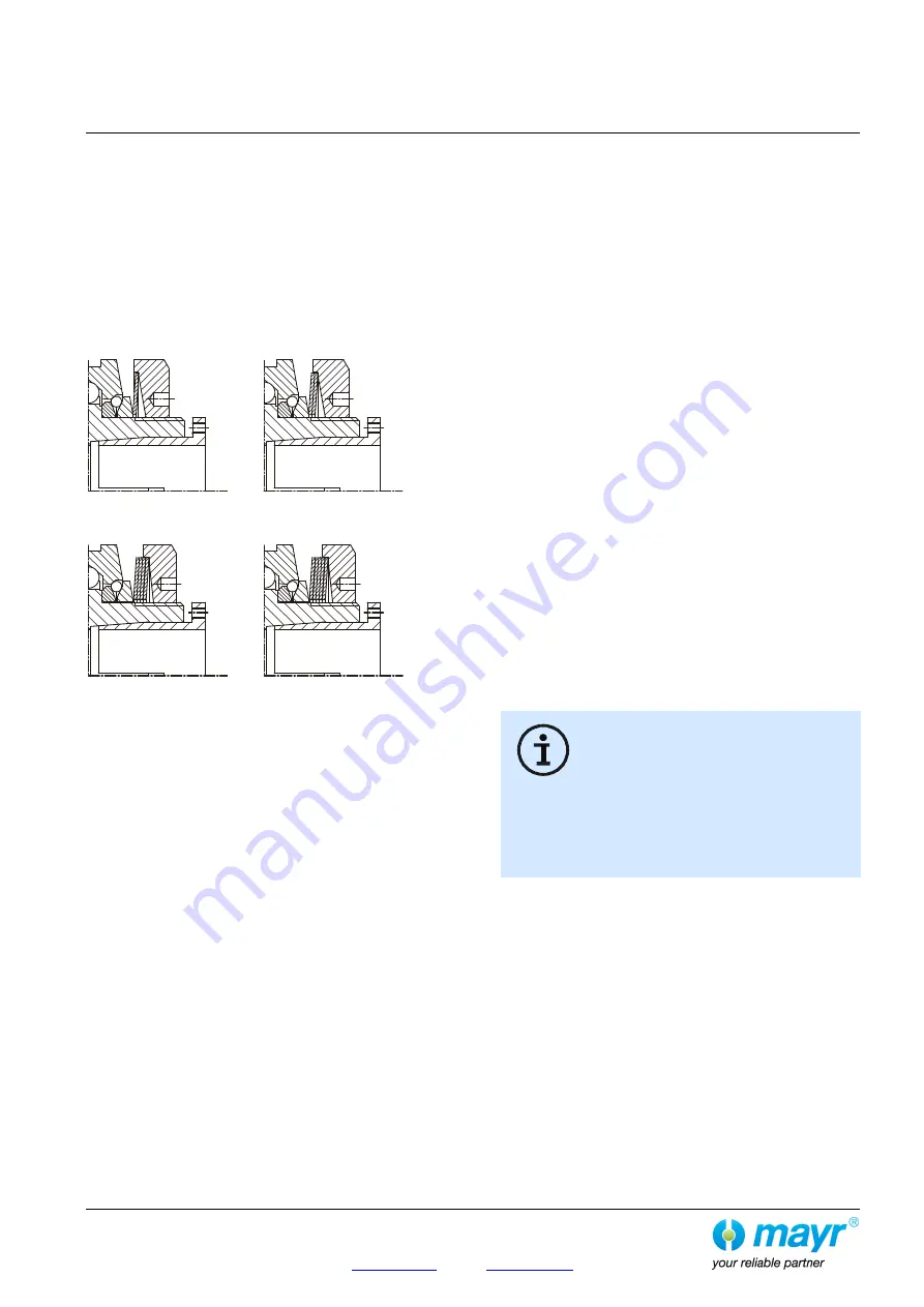
Cup Spring Layering (Fig. 6) 

Correct cup spring layering is a prerequisite for problem-free 
clutch function and torque adjustment.  
 
For the lower torque range, 

one

 cup spring  

(Type 49_.

5

_ 4._),  

for the medium torque range, 

two

 cup springs (Type 49_.

6

_ 4._),  

for the high torque range, 

four 

cup springs  

(Type 49_.

7

_ 4._) 

and for the maximum torque range  

five 

cup springs (Type 49_.

8

_ 4._) are installed. 


1x layered 

2x layered 


Type 49_.

5

_4._ 

Type 49_.

6

_4._ 


4x layered 

5x layered 


Type 49_.

7

_4._ 

Type 49_.

8

_4._ 

Fig. 6 


Mounting onto the Shaft 

EAS

®

-Compact

®

 clutches include cone bushings, shrink disks, 

clamping hubs or keyways as part of the standard delivery. 

During installation of cone bushings, shrink disks or 
clamping hubs, please observe the following: 

  Recommended shaft tolerance for cone bushings: h6 

  Recommended shaft tolerance for clamping hubs: h6 

  Recommended shaft tolerance for shrink disk hubs: g6 

  Shaft surface: finely turned or ground  

(Ra = 0.8 µm). 

  Shaft material: yield point at least 400 N/mm

2

,  

e.g. C45 +QT, 42QT. 

  Degrease or remove conserving layers on the shafts and 

bores before installing the clutch. 

Greasy or oily bores or shafts do not transmit the 
torques defined in the catalogue.


  Mount the clutch or clutch hubs onto both shaft ends using a 

suitable device and bring it / them into the correct position. 

  Tighten the tensioning screws (13) of the cone bushing (15) 

in 2 steps cross-wise and then in 3 to max. 6 tightening 
sequences evenly using a torque wrench to the torque stated 
in Table 5. 

  Type 494.-: 

Tighten the tensioning screws (22) in the shrink disks (20.1) 
stepwise (in 3 to max. 6 tightening sequences) and cross-
wise evenly using a torque wrench to the torque stated in 
Table 5. 

  Type 496.-: 

Tighten the tensioning screws (34.2) in the shrink disks 
(34.1) using a torque wrench evenly and one after the other 
in max. 6 sequences to the torque stated in Table 5. 

  The transmittable torques of the shaft-hub connection are 

dependent on the bore diameter and the quality of the drive 
shafts used. Please observe the respective transmission 
tables in the valid and applicable product catalogue. 

The clutch or clutch hub carries out an axial 
movement in the direction of the cone bushing 
(15) when tightening the cone bushing (15). 
Because of this effect, please ensure that on the 
EAS

®

-Compact

®

 clutch with steel bellows (Type 

493._ _ 4.0), first one cone bushing is completely tightened 
(e.g. Item 15), then the other (steel bellows) side (Item 24,  
page 3).  
Please also ensure during installation of Type 493._ _4.0 that 
no axial pressure is placed on the steel bellows (can cause 
damage). 


De-installation 


of the Cone Bushings and Shrink Disks 

In the cone bushings and the shrink disks, there are tapped 
extracting holes next to the tensioning screws. 

1) 

Loosen all tensioning screws by several thread turns. 

2) 

Screw out the tensioning screws located next to the tapped 
extracting holes and screw them into the tapped extracting 
holes up to their limits.  
Then tighten these screws until the tensioning connection 
loosens. 


Содержание EAS-Compact 49 . 4 Series

Страница 1: ...l Data Type 493 _ _ 4 0 Page 7 Technical Data Type 494 _ _ 4 _ Page 8 Technical Data Type 496 _ _ 4 _ Page 9 Design Scope of Delivery State of Delivery Function Re engagement Page 10 Output Elements I...

Страница 2: ...uation this product is not suitable for use in areas where there is a high danger of explosion This statement is based on the ATEX directive DANGER If the EAS clutches are modified If the relevant sta...

Страница 3: ...e 1 D 87665 Mauerstetten Germany Tel 49 8341 804 0 Fax 49 8341 804 421 Page 3 of 19 www mayr com E Mail info mayr com Fig 1 Stroke Type 494 _14 _ Type 494 _04 _ Type 494 _24 _ Type 493 _34 0 Type 493...

Страница 4: ...h flange and clamping hub 8 Steel ball 9 Cup spring Additional parts for Type 496 10 Supporting ring Item Name 11 Thrust ring 28 Disk pack 12 Steel ball 29 Connection plate 13 Hexagon head screw 30 He...

Страница 5: ...45 28 40 3 4 5 35 55 32 50 Table 3 Type 49_ 5_4 _ Type 49_ 6_4 _ Type 49_ 7_4 _ Type 49_ 8_4 _ Size Maximum torque MG Nm Inspection dimension a Fig 10 at approx 70 MG mm Maximum torque MG Nm Inspectio...

Страница 6: ...l torque TKN steel bellows coupling Type 493 Nm Bores steel bellows side Type 493 _14 _ mm Type 493 _24 _ mm Type 493 _34 _ mm Size Axial K a mm Radial K r mm Angular K w 01 0 4 0 15 2 50 9 20 9 20 12...

Страница 7: ...on shrink disk hubs frictional locking Type 494 _14 _ d4 dependent on bore suitable for tolerance constellation F7 k6 for clamping hubs and H7 k6 for shrink disk hubs Size 15 16 19 20 22 24 25 28 30...

Страница 8: ...on shrink disk hubs frictional locking Type 496 _14 _ dependent on bore suitable for tolerance constellation H7 g6 Size 19 20 22 24 25 28 30 32 35 38 40 42 45 48 50 52 55 60 65 70 01 150 150 150 150 1...

Страница 9: ...his means that no re engagement impacts or metallic sliding movements occur on the clutch torque transmission geometries when using this clutch variant In order to make the clutch ready for operation...

Страница 10: ...ing hub Type 490 _ _ 4 1 Fig 3 is recommended for extremely wide output elements or for elements with small diameters On very small diameters the output element is screwed together with the clutch pre...

Страница 11: ...able device and bring it them into the correct position Tighten the tensioning screws 13 of the cone bushing 15 in 2 steps cross wise and then in 3 to max 6 tightening sequences evenly using a torque...

Страница 12: ...ot be transferred via the steel bellows danger of bellows deformation Fig 7 Joining Both Clutch Components 1 20 Type 494 _ _ 4 _ Figs 1 and 7 The flexible elastomeric element 19 is pre tensioned betwe...

Страница 13: ...nd 13 refer to clutch operation at nominal torque an ambient temperature of 30 C and an operating speed of 1500 rpm If the clutch is operated in other or more extreme operating conditions please obser...

Страница 14: ...ub 1 facing side as shown in Fig 10 Please see Table 3 for the respective values Turning the adjusting nut 4 clockwise causes a reduction in torque Turning it anti clockwise causes an increase in torq...

Страница 15: ...rrectly Contactless limit switch mounting example Fig 13 Maintenance and Maintenance Intervals Maintenance work which should be carried out after 2000 operating hours after 1000 disengagements or at t...

Страница 16: ...he system out of operation 2 Inspect the clutch at the place of manufacture Worn disengagement mechanism Running noises in normal operation Insufficient clutch securement 1 Set the system out of opera...

Страница 17: ...3 Tighten the tensioning and clamping screws for axial hub securement and the connection screws to the required torque or tighten the locking set screw and secure it against self loosening using seali...

Страница 18: ...Make sure that further physical changes to the elastomeric element can be ruled out The ambient or contact temperatures permitted for the elastomeric element are exceeded 1 Set the system out of opera...

Страница 19: ...crew and secure it against self loosening using sealing lacquer 4 Check the clutch for wear Disk pack breakage Disk pack breakage due to high load impacts overload 1 Set the system out of operation 2...

Отзывы: