Installation and Operational Instructions for EAS
®
-compact
®
Ratchetting clutch, Type 49_._ _0._
Sizes 01 to 3
Synchronous clutch, Type 49_._ _5._
Sizes 01 to 3
(B.4.14.EN)
17/03/2021 TK/NU/GC/GF/SU
Chr. Mayr GmbH + Co. KG
Eichenstraße 1, D-87665 Mauerstetten, Germany
Phone: +49 8341 804-0, Fax: +49 8341 804-421
Page 17 of 22
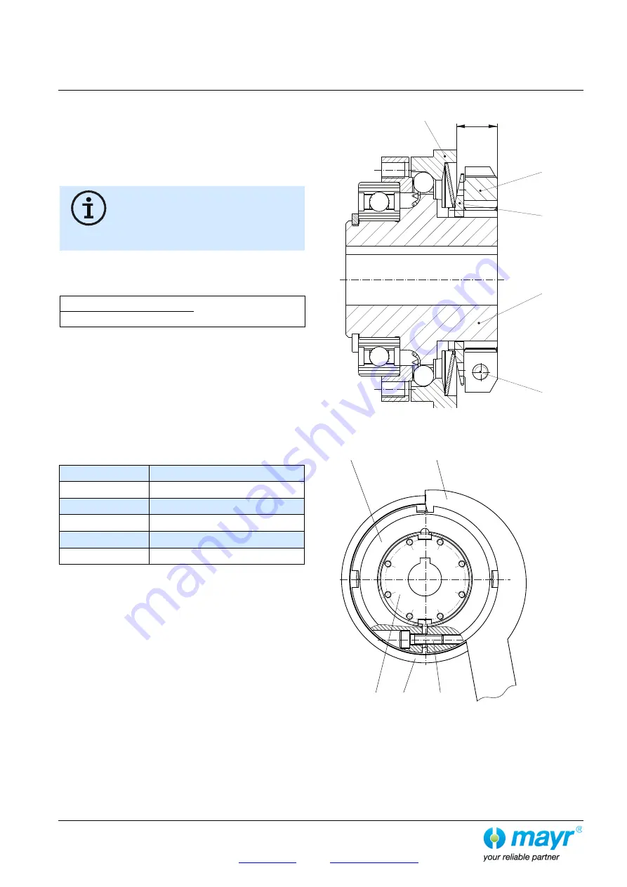
The following applies to adjusting nut with radial
clamping (option):
It is possible to check the
"Spring operation in the operating
range"
(Fig. 9/ page 15) using the dimension "a" (distance from
the adjusting nut (5.1) facing side to the thrust washer (3) facing
side, as shown in Fig. 12).
Please see Table 3 for the respective values (values in
brackets).
Turning the adjusting nut (5.1) clockwise
causes a reduction in torque.
Turning it anti-clockwise causes an increase in
torque.
You should be facing the adjusting nut (5.1) as
shown in Fig. 13.
Adjusting the torque for adjusting nut with radial clamping
a) Please convert the required torque using the formula below
into percent of the maximum adjustment value (see Table 3).
Required torque adjustment
x 100 = Adjustment in %
max. adjustment value
b) Loosen the cap screw (10.1) in the adjusting nut (5.1).
c) Turn the adjusting nut (5.1) using the adjustment scale (10)
engraved on the outer diameter clockwise or anti-clockwise
using a hook wrench until the required torque is reached.
d) The required torque results from the marking overlap on the
locking ring (4) and the percent value on the adjusting nut
(5.1).
e) Paint the cap screw (10.1) with Loctite 243 and screw it into
the adjusting nut (5.1) as protection against twisting using
the tightening torque according to Table 17.
Table 17
Size
Tightening torque Item 10.1
01
2.8 Nm
0
5.5 Nm
1
9.5 Nm
2
9.5 Nm
3
23 Nm
Fig. 12
Fig. 13
a
5.1
10.1
1
4
3
5.1
10.1
1
3
Hook wrench


