Only connect the MEW-OS100LNW to a Single Pole Circuit.
The MEW-OS100LNW is not suitable for 3-way switching. If the existing wiring does not
match the description for a Single Pole Circuit, you should consult with a qualified
electrician.
3. Prepare the Wires.
Tag the wires currently
connected to the existing switch,
so that they can be identified later.
Disconnect the wires.
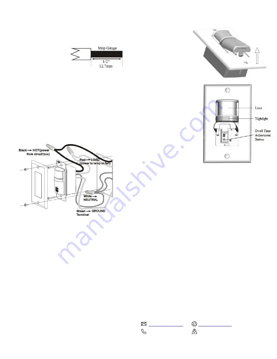
Make sure the insulation is stripped off the wires to expose their copper cores to the
length indicated by the ”Strip Gauge,” in Fig. 3 ( approx. 1/2 inch).
4. Wire the sensor.
Cap the sensor switch wires securely using the wire nuts provided. See Fig. 4.
▪ Connect the green or non-insulated (copper) GROUND wire from the circuit to the
green wire on the sensor switch.
▪ Connect the NEUTRAL wire from the circuit to the white wire on the sensor switch.
▪ Connect the power wire from the circuit box (HOT) to the black wire on the switch.
▪ Connect the power wire from the lamp or fan (LOAD) to the red wire on the switch.
Fig. 4: Sensor Orientation, wire connections
and wall box assembly
5.
Put the MEW-OS100LNW in the wall Box with the lens positioned
above the manual button (lens at top, button at bottom).
Secure it to the wall box with the screws provided.
6. Attach the new cover plate.
7. Restore power to the circuit.
Turn ON the breaker or replace the fuse.
1 YEAR WARRANTY
Maxxima extends a 1 year limited warranty to the original purchase that the products
listed are free from defects in material and/or workmanship only. Maxxima will replace
any warranteed product to the original consumer/purchaser if the product fails because
of defects due to workmanship and/or materials within the limited warranty period.
Limited warranty is not transferable and applies to the original installation of the
Maxxima product. This offer does not constitute in any way a product guarantee and
Maxxima does not hereby assume any obilgation whatsoever beyond sending a free
replacement product.
SENSOR ADJUSTMENT & PROGRAMMING
To program the MEW-OS100LNW,
use controls located under the
standby button. The wall switch
cover plate must be opened to
gain access to the adjustment
button under the standby button.
To adjust the time delay:
1). Depress “U” shape tab at
bottom of control and at the
same time swing open the cover.
2). Adjust the desired delay
off time behind the cover.
Press the Dwell Time Adjustment button.
(“
+
”or “
-
“ button)
When it indicates “1”, the delay time is
1 minute ( minimum).
“1”- 1 minute
“5”- 5 minutes
“15”- 15 minutes
“30”- 30 minutes
“60”- 60 minutes
“M”- Manual Mode
3) After time was set, snap
cover back until it latch shut.
4) In Manual Mode (M), the load will turn ON and OFF when the manual button is
pressed and operates as a regular ON/OFF switch.
5) If the load is turned OFF manually after the sensor turns it ON, the occupancy sensor is
disabled for 1 minute and would not detect any occupance. The sensor is re-enabled
after 1 minute and resumes detection.
TROUBLESHOOTING
Load will not turn ON (nightlight is visible):
Press manual button. The load should turn ON. If not:
• Check the light bulb and/or motor switch on the fan mechanism.
• Turn off power to the circuit then check wire connections.
Load will not turn ON (nightlight is NOT visible):
• Check the light bulb and/or motor switch on the fan mechanism.
• Make certain that the circuit breaker is on and functioning.
• Turn off power to the circuit then check wire connections.
Load will not turn OFF:
• Make sure no motion is occurring in the coverage area until the set time period.
• Hot air currents and heat radiating devices can cause false detection. Make sure the
sensor is at least 6 feet (2 meters) away from devices that are a significant heat source
(e.g., heater, heater vent, high wattage light bulb).
• Push the manual button. If load does not turn off, turn off power to the circuit and
then check wire connections.
CONTACT US
866-MAXXIMA (629-9462)
125 Cabot Court, Hauppauge, NY, 11788
Fig. 3: Wire Stripping
Fig. 5: Sensor Adjustment Controls


