


User Manual
EN
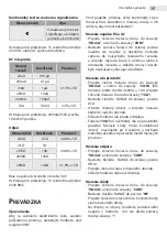
Continuity test with audio signal
Range
Description
A built-in beeper
signals if the
resistance is below
70±20Ω
Overload protection: 15 seconds maximum
250V DC/AC peak value
DC current
Range
Resolution
Accuracy
20uA
0.01μA
±1.5% +3D
200uA
0.1μA
2mA
1μA
20mA
10μA
200mA
100μA
10A
10mA
±2% +5D
Overload protection: 200mA/250V fuse and
10A/250V fuse
Max. input current: 10A (max. 6 sec.)
Resistance
Range
Resolution
Accuracy
200Ω
0.1Ω
±0.8% +5D
2kΩ
1Ω
±0.8% +3D
20KΩ
10Ω
200KΩ
100Ω
20MΩ
10kΩ
±1.0% +15D
Max. open circuit voltage: 3.0V
Overload protection: 15 seconds maximum
250V RMS
o
peration
WARNING
To avoid electric shock and damage to the
device do not measure voltage exceeding 300V!
Always verify the intactness and insulation of
the measuring wires, connectors and other units
before measuring!
DC and AC voltage measuring
•
Connect the red measuring wire to the “
VΩmA
”
connector and the black one to the “
COM
”
connector.
•
Set the function and range switch to the desired
voltage position. If the voltage is unknown,
set the switch to the highest available range,
connect the wires to the device and the circuit
and reduce the range until the value shown is
correct.
DC current measuring
•
Connect the red measuring wire to the “
VΩmA
”
connector and the black one to the “
COM
”
connector. (For measuring current between
200mA and 10A connect the red wire into the
“
10A
” connector).
•
Set the RANGE switch to the desired DCA
position
•
Open the measured circuit and connect to it
serially.
•
Read the current value from the screen.
•
The “
10A
” function is designed for limited time
use only. The measuring wire should only be
connected to the circuit for the maximum of 6
seconds and allow a few seconds in between
measurements.
Resistance measuring
•
Connect the red measuring wire to the “
VΩmA
”
connector and the black one to the “
COM
”
connector.
•
Set the RANGE switch to the desired OHM
position.
•
Connect the measuring wires to the circuit.
•
Read the resistance value from the screen.
Diode measuring
•
Connect the red measuring wire to the “
VΩmA
”
connector and the black one to the “
COM
”
connector.
•
Set the RANGE switch to the “ ” position.
•
Connect the red measuring wire to the anode
of the measured diode and the black one to the
cathode.
•
The opening voltage dropback is shown on
the screen in mV-s. If the diode is closing, the
screen shows “1”.