background image

4

connector on the rear of your computer system. The video output
connector on your computer may be either in a location similar to
Figure 2-2

 or on an expansion board. Secure the cable to the

computer using the thumbscrews on the 15-pin connector.

· Attach the power cord to the monitor and plug it into an AC outlet.
· The monitor is now ready for use.

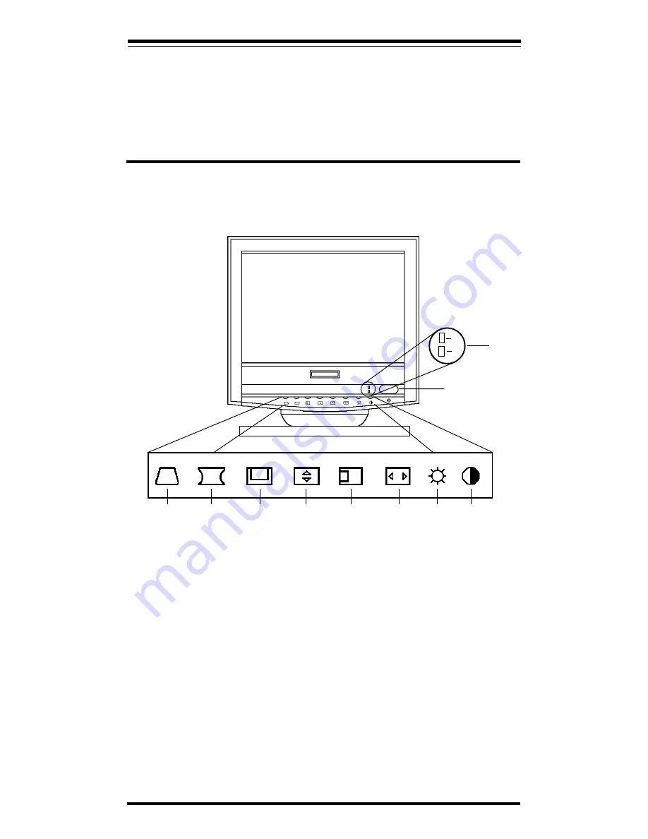
Section 3 - Monitor Controls and LEDs

1.

Power Indicators: LEDs A and B indicate the state of the Monitor.

LED A On (green)  Normal operations.

LED A flashing  DPMS “STAND-BY” mode.

LED B On (orange)  DPMS “OFF” mode.

2.

Power Switch:Push to turn the monitor ON, push again to turn the
monitor OFF.

3.

Trapezoid: Adjusts the angle of the sides of the display to make the
display rectangular.

4.

Pincushion Adjusts the curvature of the sides of the display to make
the sides straight.

5.

Vertical-Position: Adjusts the vertical position

6.

Vertical-Size: Adjusts the display height

7.

Horizontal-Position :Adjusts the horizontal position

8.

Horizontal-Size: Adjusts the display width.

A
B

1

2

3

8

9

10

7

6

5

4

Figure 3-1 Controls and LEDs

Содержание XT4861

Страница 1: ...XT4861 Features 1024 x 768 Non Interlaced 28 mm Dot Pitch 72 Hz Refresh Rate VGA SVGA Power Saving Operation VESA DPMS Full Screen Display Easy Access Front Controls Unlimited Palette of Colors Plug a...

Страница 2: ...all be easily accessible Follow all instructions and warnings on the product Do not place the product on an unstable cart Operate from power source indicated on the label Do not allow anything to rest...

Страница 3: ...l shine directly on the monitor Your monitor should be placed just below eye level for optimum viewing Allow adequate ventilation around the monitor so that heat from the monitor can properly dissipat...

Страница 4: ...s to normal operation Section 2 Installation 2 1 Attaching the Base Carefully place the monitor on its side or top Insert the hooks on the swivel base into the slots in the bot tom of the monitor Push...

Страница 5: ...he state of the Monitor LED A On green Normal operations LED A flashing DPMS STAND BY mode LED B On orange DPMS OFF mode 2 Power Switch Push to turn the monitor ON push again to turn the monitor OFF 3...

Страница 6: ...No picture power indicator A flashing Monitor is in DPMS STAND BY mode Press a key or move the mouse No picture power indicator B on Monitor is in DPMS OFF mode Press a key or move the mouse Image is...

Страница 7: ...4 25 in H x 14 64 in D Specifications subject to change without notice Appendix B Video Cable Pinout Appendix C Three Year Warranty MAXTECH warrants to the original buyer of this product against defec...

Страница 8: ...er controls 3 Payment of shipping charges HOW TO OBTAIN WARRANTY SERVICE In the event the product requires service call the MaxTech Service Center at 562 921 4438 between 9 00 a m and 6 00 p m PST Mon...

Страница 9: ...apply to you HOW STATE LAW RELATES TO THE WARRANTY This warranty gives you specific legal rights and you may also have other rights which vary from state to state Appendix D Notices FCC Class B Statem...

Страница 10: ...ques telles que prescrites par le R glement sur le brouillage radio lectrique tabli par le minist re des Communications du Canada L exploitation faite en milieu r sidentiel peut entra ner le propri ta...

Отзывы: