background image

  1.  Launch the X-CTU Software: 

(Start --> Programs --> MaxStream --> X-CTU)

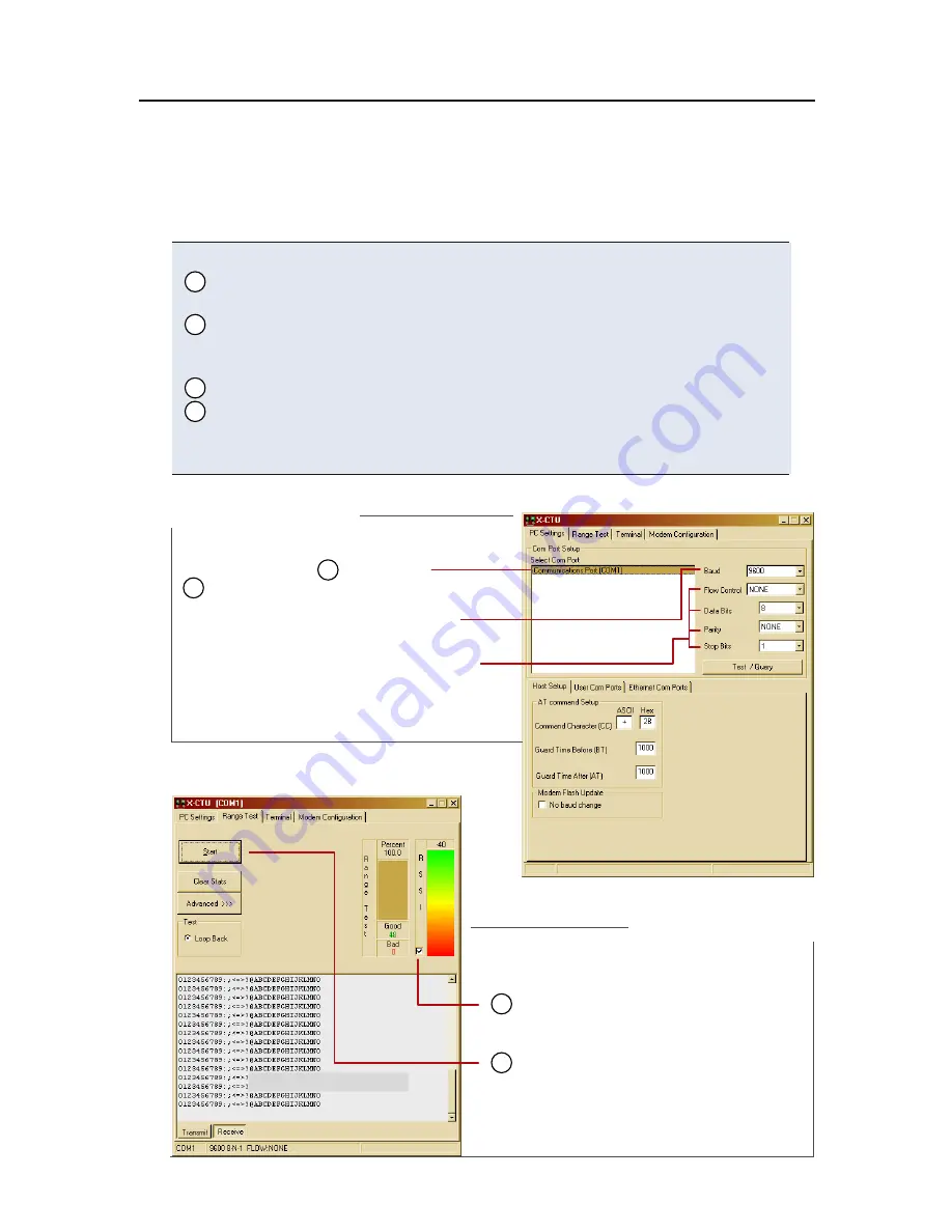
    Under the "PC Settings" tab [Figure 3], select the PC serial com port 
    from the list that will be used to connect to Radio1.
    Select the Baud rate that matches the fixed RF data rate of Radio1. 
    Use default values for remaining fields. [Figure 3]
  4.  Click on the "Range Test" tab. [Figure 4]
    (Optional) Check the box in the "RSSI" checkbox to enable its display. 
    Click the "Start" button to begin the range test.
  7.  Move Radio2 (with loopback connector) away from Radio1 to find the 
    module's maximum range. 

Figure 4.  Range Test tab

Figure 3.  PC Se�ings tab

2

3

5
6

3

Use the "PC Settings" and "Range Test" tabs of the X-CTU Software to:
  •  Assign which PC Serial Com Port to use when communicating with 
 

XStream module assemblies [step 2 of "Range Test"]

  •  Measure XStream OEM RF Module's range [steps 1-7 of "Range Test"]

Range Test Execution

Range Test

PC Com Port

Default Values

Refer to XStream Module part number

to determine its default (& fixed) RF data rate:

Other Default Values:

Flow Control  =  None

Data Bits   

=  8

Parity     =  None

Stop Bits   =  1

5

RSSI 

check box

RSSI 

stands for "Received Signal Strength Indicator". 

6

Start/(Stop) 

button

(Packet Information)

2

X09-009...  = 

9600 bps

X09-019...  = 

19200

X24-009...  = 

9600

X24-019...  = 

19200

Содержание XStream

Страница 1: ...lopment Kit Quick Start Guide Introduction Range Test Setup Range Test Execution Tips and Suggestions Contact MaxStream www maxstream net 2005 MaxStream Inc All rights reserved MD0007 Create a Long Range Wireless Link in Minutes ...

Страница 2: ...d DIP Switches to RS 232 Mode Switch 1 is ON up and the remaining 5 switches are OFF down Figure 5 2 Mount each XStream Module to a MaxStream Interface Board Figure 1 Assemblies will be referred to as Radio1 and Radio2 3 Attach RPSMA antenna to the XStream Module that does not have an attached wire antenna 4 Connect Radio1 to a PC using the included RS 232 cable Figure 2 5 Attach the serial loopba...

Страница 3: ...ind the module s maximum range Figure 4 Range Test tab Figure 3 PC Se ings tab 2 3 5 6 3 Use the PC Settings and Range Test tabs of the X CTU Software to Assign which PC Serial Com Port to use when communicating with XStream module assemblies step 2 of Range Test Measure XStream OEM RF Module s range steps 1 7 of Range Test Range Test Execution Range Test PC Com Port Default Values Refer to XStrea...

Страница 4: ...uch as automatic meter readers fleet management devices remote weather stations and a host of other applications When creating a wireless link consider the following Use the male to male NULL modem adapter to connect Radio2 to a target serial device Figure 6 Pin signals crossover inside the adapter To verify serial cabling is functioning properly insert a female to female NULL modem adapter in pla...

Страница 5: ... Electronics Authorized Distributor Click to View Pricing Inventory Delivery Lifecycle Information DIGI X09 009 DK X09 019 DK X24 009 DK X24 019 DK X24 009 DK INT X24 019 DK INT Digi International X09 001NST ...

Отзывы: