Bottom cap (item 46). Grease the o-ring (item 25) and mount it on the bottom cap (item 46).
Grease and place the o-ring (item 9) into the bottom cap (item 46).
Страница 1: ...maintenance and repair instructions for MAXIMATOR Air Amplifier SPLV2 MAXIMATOR GmbH Walkenrieder Straße 15 37449 Zorge Phone 49 55 86 80 30 Fax 49 55 86 8 03 40 E Mail Info maximator de Homepage www maximator de ...
Страница 2: ...ifier stations 6 6 Installation Operation 6 6 1 Pneumatic amplifiers 7 7 Maintenance 7 8 Maintenance tips 8 9 Compressed air quality 8 10 Guarantee 9 11 Amplifier Disassembling 10 11 1 Check valve disassembling 19 11 2 Spool valve disassembling 23 12 Amplifier assembling 25 12 1 Check valve assembling 25 12 2 Air drive section assembling 29 12 3 Spool valve assembling 42 ...
Страница 3: ...ct the intake and outlet connectors The supply air flows through check valve b from connector A and enters compression chamber I and II The drive pressure connector PL fills drive chamber II via the control slide valve as the pressure is released from the drive chamber I By means of its motion the piston reduces the volume of the compression chamber II and the pressure is increased The operating p...
Страница 4: ...ce Graph SPLV 2 0 500 1000 1500 2000 2500 0 2 4 6 8 1 0 1 2 1 4 1 6 1 8 2 0 Outlet Pressure bar Outlet Flow l N min 0 500 1000 1500 2000 2500 Air Consumption l N min Outlet Flow at 2 bar Outlet Flow at 4 bar Outlet Flow at 6 bar Outlet Flow at 8 bar Outlet Flow at 10 bar Air Consumption at 2 bar Air Consumption at 4 bar Air Consumption at 6 bar Air Consumption at 8 bar Air Consumption at 10 bar 6 ...
Страница 5: ...4 Dimension and Connection Drawing ...
Страница 6: ...unctional checks and be easily accessible Measurement devices should be included to monitor the compressor pressure The provisions regulating pressure tanks should be considered when using a pressure tank that is topped up by another object or device 5 2 Pneumatic amplifier stations Pneumatic amplifier stations are devices which meet the safety regulations described in the pneumatic tank provision...
Страница 7: ...lve is branched off from the pneumatic connection The pneumatic amplifier begins with a pressure increase if the operating pressure pb is equal to the intake pressure pa see illustration 2 Pneumatic amplifiers with external pilot air intake valves have a connector marked with X possible with SPLV 2 and GPVL 2 The conduits which are branched off from the intake pressure can be used for the installa...
Страница 8: ... particle size 5 µ maximum particle concentration 5 mg m3 Dew point 10 C water content of 9 4 g m3 to 2 C water content of 5 6 g m3 Oil content 1 0 to 5 mg m3 By observing this drive air quality an optimum life time of the seals and packing will be achieved Operating time All MAXIMATOR products are designed for intermittent operation Please consult factory for special applications Technical data A...
Страница 9: ... sealing kits can be gathered from the drawings like the respective purchase order numbers Make sure to indicate the compressor serial number when ordering spare parts The serial number is located in the machine plate of the compressor and is also punched into the compressor housing as a 6 digit number It goes without saying that the most convenient approach for you is to ship a defective unit to ...
Страница 10: ...ling Loosing and disassembling the exhaust muffler item 14 Unscrew and disassembling of the two screws item 46 Tool size 6 Disassemble the connection block item 48 and draw the air tube item 51 out of the spool valve housing ...
Страница 11: ...Loosen the five socket head screws item 13 12 in the spool valve housing Disassemble the spool valve housing Loosen the two socket head screws item 44 and 43 and disassemble the base plate item 42 ...
Страница 12: ...ring washer item 55 from the stud bolts Carefully separate the bottom cap item 46 maybe by means of light hammer taps with a plastic hammer from the air cylinder item 26 and disassemble the air tube item 24 Disassemble the bottom cap item 46 compl from the air cylinder item 26 ...
Страница 13: ... cap item 1 by means of light taps with a plastic hammer from the air cylinder item 26 Loosen the two hexagon screws item 33 Key size 19 Disassemble the both hexagon nuts item 33 and u washers item 32 from the piston rod item 27 ...
Страница 14: ... separation plate item 34 maybe by means of light taps with a plastic hammer Carefully separate the second air cylinder item 26 in the same way Pull the piston rod item 27 out of the air separation plate item 34 and disassemble the two o ring item 31 on both ends ...
Страница 15: ...Remove the piston sealing ring item 30 from the piston item 28 Remove the o ring item 29 from the piston item 28 Dismantle the o ring item 25 from the bottom cap item 46 ...
Страница 16: ...tle the o ring item 23 out of the groove in the bottom cap item 46 Loosen completely and unscrew the pilot valve screw item 16 Disassemble the gasket item 21 the spring item 18 and pilot valve tappet item 19 ...
Страница 17: ...ing item 25 from the top cap item 1 Dismantle the o ring item 23 out of the groove in the top cap item 1 Loosen completely and unscrew the pilot valve screw item 15 Disassemble the gasket item 21 and the spring item 18 ...
Страница 18: ...Dismantle the pilot valve tappet item 19 out of the top cap item 1 Air separation plate item 34 with the compl check valves ...
Страница 19: ...11 1 Check valve disassembling Remove the locking ring item 41 Remove the retainer ring item 40 Remove the spring holder item 39 ...
Страница 20: ...Remove the spring item 38 Remove the check plate item 37 Remove the check seat item 36 Separate the o ring item 9 from the check seat item 36 ...
Страница 21: ...Remove the locking ring item 41 Remove the retainer ring item 40 Remove the check seat item 36 Separate the o ring item 9 from the check seat item 36 ...
Страница 22: ...Remove the check plate item 37 Remove the spring item 38 Remove the spring holder item 39 Dismantle the o ring item 25 from the air separation plate item 34 ...
Страница 23: ...lve housing item 3 Caution Make sure to avoid damaging the spool Preferably use a plastic or wooden mandrel The O rings on the spool valve sleeve are statically sealing i e they are not subject to wear and tear This means that the spool valve sleeve has only to be dismantled when it is damaged Use a mandrel to force the spool valve sleeve out of the spool valve housing Caution Make sure to avoid d...
Страница 24: ...Remove the O rings from the spool and if applicable from the spool valve sleeve Remove the O ring item 6 from the sealing cap ...
Страница 25: ...s item 25 and assemble on the air separation plate item 34 Assemble the spring holder item 39 into the air separation plate item 34 Assemble the spring item 38 into the air separation plate item 34 Assemble the check valve plate item 37 into the air separation plate item 34 ...
Страница 26: ...ng item 9 on the check valve seat item 36 Assemble the valve seat into the air separation plate item 34 Assemble the retaining ring item 40 into the air separation plate item 34 Protect the first check valve by assembling the snap ring item 41 ...
Страница 27: ...eat 36 Assemble the check valve seat item 36 into the air separation plate item 34 Put the check valve plate item 37 into the air separation plate item 34 Put the spring item 38 into the air separation plate item 34 and on the on the top side of the check valve plate item 37 ...
Страница 28: ...g item 40 on the top side of the spring holder into the air separation plate item 34 Protect the second check valve by the snap ring item 41 The picture show the compl pre assembled air separation plate Please respect and attend the direction of check valve ...
Страница 29: ... picture show the top cap item 1 Grease the pilot valve tappet item 19 Assemble the pilot valve tappet item 19 in the top cap item 1 Put the pilot valve spring item 18 into the pilot hole on the top side of cap item 1 Assemble the gasket item 17 ...
Страница 30: ...Insert and tighten the pilot valve screw item 15 Grease the o ring item 25 and assemble the same on the top cap item 1 ...
Страница 31: ...Grease the o ring item 23 and insert it into the top cap item 1 Insert the damper item 58 into the top cap item 1 by means of light taps with a plastic hammer Completed top cap item 1 ...
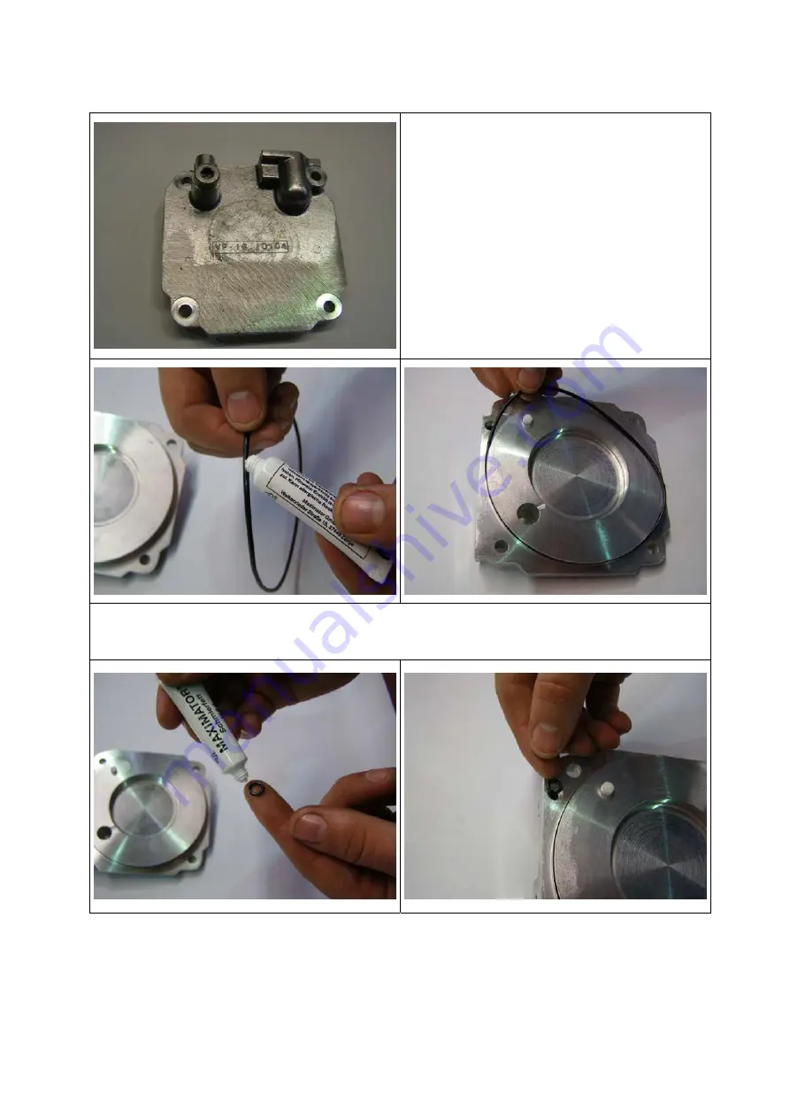
Страница 32: ...Bottom cap item 46 Grease the o ring item 25 and mount it on the bottom cap item 46 Grease and place the o ring item 9 into the bottom cap item 46 ...
Страница 33: ...m 19 and place it into the bottom cap item 46 Completed bottom cap item 46 The left picture show the separate parts of air piston consisting of the slide ring item 30 the o ring item 29 and the piston item 28 Grease the o ring item 29 ...
Страница 34: ...Slip the o ring item 29 on the piston item 28 Attach carefully the slide ring item 30 on the piston item 28 Grease the two air cylinders item 26 ...
Страница 35: ...Insert the pre assembled piston into the air cylinder item 26 Grease the bushing item 35 Grease the two o rings item 31 for the piston rod item 27 ...
Страница 36: ...Attach the o rings item 31 on the piston rod item 27 Insert the pre assembled piston rod into the air separation plate Push the air cylinder item 26 over the piston item 28 ...
Страница 37: ...ghten the nut item 33 Push the air cylinder item 26 and the air separation plate item 34 together until the air cylinder fits closely to the bottom cover Push the air cylinder item 26 over the piston item 28 Attach the washer item 32 ...
Страница 38: ... the air separation plate item 34 together until the air cylinder fits closely to the bottom cover Tighten the two nuts item 33 by two keys Attach the top cap item 1 and push it to the air cylinder item 26 until both parts fits closely ...
Страница 39: ...osely Insert the air tube item 24 and push the bottom cap item 46 and the top cap item 1 together Attach the first longer tie rod item 53 with u washer item 54 and spring washer item 55 see red arrow Then attach also the 3 shorter tie rods item 52 with u washer item 54 and spring washer item 55 ...
Страница 40: ...Attach the washer item 54 the spring washer item 55 and the nut item 56 Attach the base plate item 42 Insert the two socket head screws item 44 and spring washer item 43 Tighten the two screws item 44 ...
Страница 41: ...orkbench for alignment and a soft hammer is used to align the bottom and top cap in parallel Then tighten the hexagon nuts crosswise with the specified torque Grease the gasket item 2 on both sides and attach it onto the top cap item 1 ...
Страница 42: ...all components for damage and replace them as required There must not be any scoring at the spool valve sleeve Grease all O rings Slip the O rings onto the spool item 7 sealing cap item 10 and if applicable the spool valve sleeve item 4 ...
Страница 43: ... motions into the spool valve sleeve If applicable grease the spool valve housing internally and install the spool valve sleeve with slight rotating motions into the spool valve housing Re insert the sealing cap item 10 into the spool valve housing item 3 and fasten it with the locking ring item 11 ...
Страница 44: ...Insert the five socket head screws item 13 with the washer item 12 into the spool valve housing item 3 Grease the o rings item 50 for the air tube item 51 ...
Страница 45: ...rings item 50 for the air tube item 51 and insert it into the spool valve housing item 3 Grease and insert the o ring item 47 into the bottom cap item 46 Attach the connection block item 48 on the bottom cap item 46 ...
Страница 46: ...Place the two socket head screws item 49 to fasten the connection block item 48 Re insert and tighten the exhaust muffler item 14 into the spool valve housing item 3 Completed air amplifier type SPLV2 ...