


23
Maxim Integrated
Evaluates: DS34S132
DS34S132 Evaluation Kit
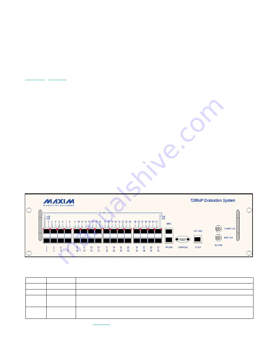
3.1 Front Panel Indicators
The unit’s LEDs are located on the front panel (see
Figure 3-1
)
lists the functions of the EV kit LED
indicators.
3.2 User Interface Software
3.2.1 Using the Control Port and an ASCII Terminal
The EV kit can be configured and monitored using an
ASCII terminal connected to the control port on the EV
kit front panel. The control port is a V.24/RS-232 asyn-
chronous DCE port terminated in a 9-pin, D-type female
connector. The EV kit continuously monitors control
port signals from the ASCII terminal and immediately
responds to any input string received through this port.
To access the user interface software using an ASCII
terminal:
1) Ensure all DS34S132 EV kit cables and connectors
are properly connected.
2) Connect the DS34S132 EV kit to a PC equipped
with ASCII terminal emulation software (for example,
Windows Hyper Terminal or PuTTY).
3) Set the port parameters of the control terminal PC to
115.2kbps, 8 bits/character, 1 stop bit, no parity. If
available, set the terminal emulator to ANSI VT100
emulation (for optimal view of system menus).
4) At the end of the initialization and self-test, system
software detects the part number of the TDMoP IC
on the internal daughter card and displays it on the
terminal screen as:
login:
The login ID is
target
and the password is
password
.
After giving the password, the screen shows:
~ $
Write the following commands in sequence as shown:
~ $ su
~ $ password: root
~ $ ./ins132
~ $ ./top32App
The
Main Configuration (S132)
menu is displayed in
the terminal.
top32App can be executed again after exiting the
Main Configuration (S132)
menu.
Figure 3-1. DS34S132 EV Kit Front Panel
Table 3-1. DS34S132 EV Kit LEDs and Controls
Note:
LINK and ACT are not shown in
Figure 3-1
.
NAME
TYPE
FUNCTION
LOS
Red LED
On: Loss of signal (LEDs on the left refer to the top port, LEDs on the right refer to the bottom port).
LOF
Red LED
On: Loss of E1/T1 synchronization has been detected.
LINK
Green LED
On: Ethernet link is connected.
Off: Ethernet link is disconnected.
ACT
Yellow LED
On: Data is being transmitted/received at the Ethernet interface.
Off: No data is being transmitted/received at the Ethernet interface.


