background image

COMMISSIONING OF DP-20/DP-30

3 - 4

SE-46C

Commissioning of the web guide controllers

www.maxcess.eu

MI 1071 1 A

Inbetriebnahme

 DP-2

030.fm

OI-TS operator interface:

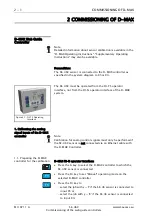
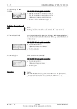
Select signal assignment 10mA

DP-20/DP-30 web guide controller:

Determine the second reference value

Press the ENTER key

The DP-20/DP-30 web guide controller returns to the user area 

if the calibration was successful.

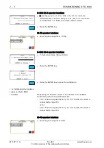
1.5. Exit menu 1K.8.3 

Simulate Analog Signals

 on 

the SE-46C

OI-TS operator interface:

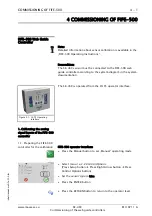
Press the CONFIRMATION button to exit menu 1K.8.3

Press the RETURN button twice to return to the operator level

2. Setting the ASC 

(Automatic Sensor Control)

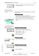
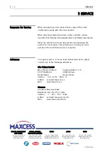
2.1. Selecting the ASC Source DP-20/DP-30 web guide controller:

DP-20 controller: select menu 3D.5.3

DP-30 controller: select menu 3D.5.4

(Manual 

 Custom 

 ASC Source)

As 

ASC source

 select Line sensor - Line edge 

§

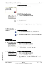
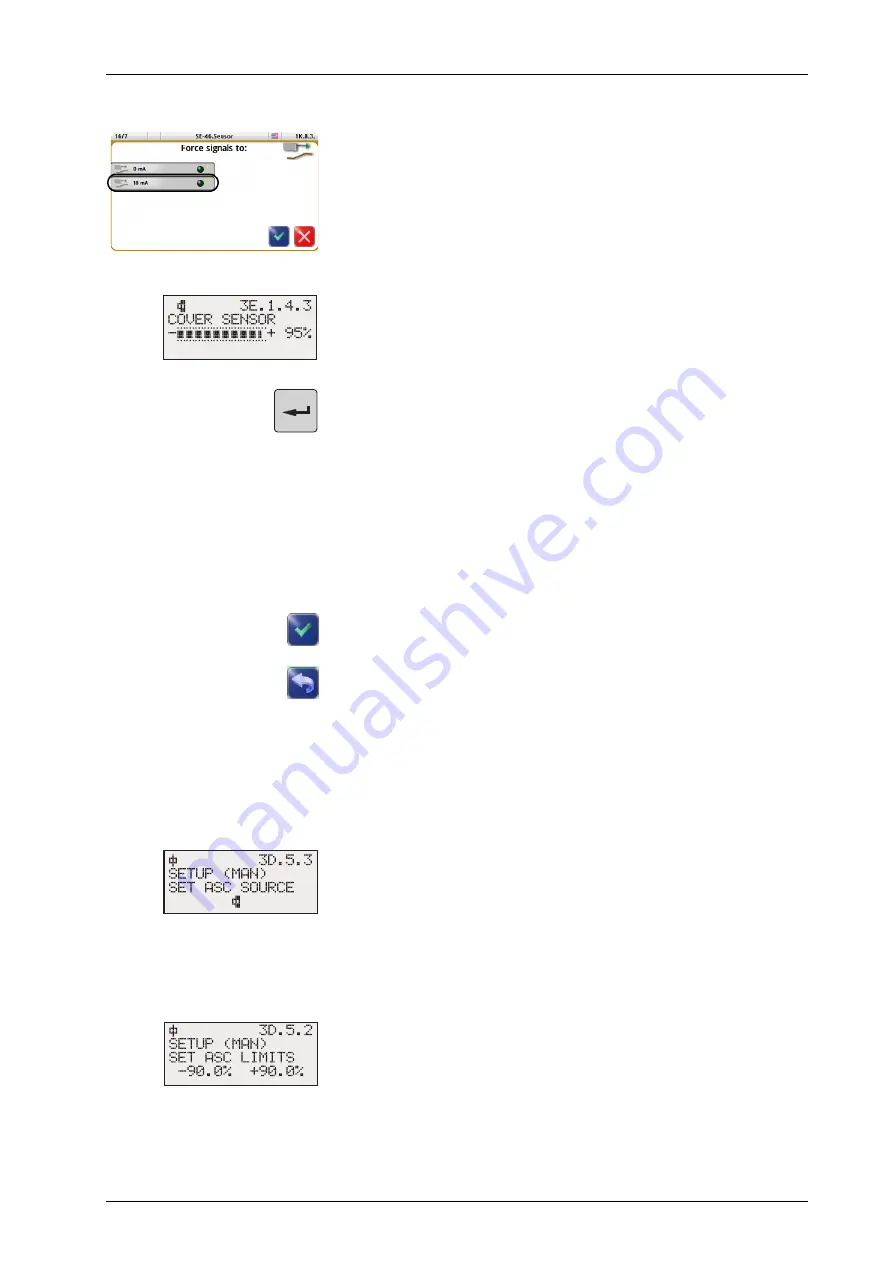
2.2. Setting ASC limits

DP-20/DP-30 web guide controller:

DP-20 controller: select menu 3D.5.2

DP-30 controller: select menu 3D.5.3

(Manual 

 Custom 

 ASC Limits)

Set the values of the 

ASC limits

 to the range from 

-90%

 to 

+90%

G

Содержание SE-46C

Страница 1: ...FIFE GUIDING SOLUTIONS FIFE SE 46C and Web Guide Controllers Commissioning Manual OI TS firmware version 002 and later MI 1071 1 A EN ...

Страница 2: ...3 Setting the polarity and gain 2 5 Operation 2 6 COMMISSIONING OF DP 20 DP 30 3 1 DP 20 DP 30 Web Guide Controller 3 1 1 Calibrating the analog signal inputs of the DP 20 DP 30 3 1 2 Setting the ASC Automatic Sensor Control 3 4 3 Setting the polarity and gain 3 5 Operation 3 5 COMMISSIONING OF FIFE 500 4 1 FIFE 500 Web Guide Controller 4 1 1 Calibrating the analog signal inputs of the FIFE 500 co...

Страница 3: ...connected to it The commissioning instructions must be kept in a safe place and must always be available throughout the service life of the SE 46C digital line sensor Note For further information and safety instructions regarding the web guide controller and sensor SE 46C please consult the relevant operating instructions in the system documentation Translation of the original Commissioning Manual...

Страница 4: ...I N operator interface of the D MAX system 1 Calibrating the analog signal inputs of the D MAX controller Note Calibration for analog control signals must only be performed if the SE 46C sensor is not connected via an Ethernet cable with the D MAX Controller 1 1 Preparing the D MAX controller for the calibration D MAX OI N operator interface Press the A key to select the D MAX controller to which ...

Страница 5: ...6C The analog signals required for the calibration are simulated by sensor SE 46C OI TS operator interface Select menu 1K 8 3 Simulate Analog Signals Press the 6 button and hold it for 2sec Press the 8 button Startup Press the 3 button Simulate Analog Signals Press the RETURN button to confirm the information in the display 1 3 Calibrating the locking signal on the D MAX controller Depending on ho...

Страница 6: ...Select signal assignment 10mA D MAX OI N operator interface 2 Reference Value Upper Limit Press the ENTER key Press the ENTER key to save the calibration 1 4 Calibrating the position signal on the D MAX controller Depending on how the sensor is connected to the D MAX Controller perform the calibration for S 02 Position signal menu 1y 5 1 2 if the SE 46 sensor is connected to input X5 or for S 04 P...

Страница 7: ...rface Select signal assignment 10mA D MAX OI N operator interface 2 Reference Value Upper Limit Press the ENTER key Press the ENTER key to save the calibration Press and hold the ESC key until you reach the user level of the D MAX controller 1 5 Exit menu 1K 8 3 Simulate Analog Signals on the SE 46C OI TS operator interface Press the CONFIRMATION button to exit menu 1K 8 3 Press the RETURN button ...

Страница 8: ...AX OI N operator interface Select menu 1y 3 y6 1 Job Settings ASC ASC State Set the ASC State to ON 3 Setting the polarity and gain Note Connection to X5 job with y J Connection to X9 job with y K 3 1 Setting the polarity The guiding direction polarity must be checked depending on the mechanical installation direction of the system and adjusted if necessary D MAX OI N operator interface Select men...

Страница 9: ...ing of the web guide controllers www maxcess eu MI 1071 1 A Inbetriebnahme D MAX fm Operation Note Depending on whether the sensor is connected to X5 or X9 operation on the D MAX Controller in Automatic operating mode will proceed with job J or K ...

Страница 10: ...Precondition The SE 46C sensor is connected to the DP 20 web guide controller on input X4 or to the DP 30 web guide controller on input X5 The calibration described here only applies to this input The SE 46C is operated from the OI TS operator interface 1 Calibrating the analog signal inputs of the DP 20 DP 30 1 1 Preparing the DP 20 DP 30 for calibration DP 20 DP 30 web guide controller Press the...

Страница 11: ...g Signals Press the 6 button and hold it for 2sec Press the 8 button Startup Press the 3 button Simulate Analog Signals Press the Return button to confirm the information in the display 1 3 Calibrating the locking signal on the DP 20 DP 30 web guide controller DP 20 DP 30 web guide controller Select menu 3D 1 4 1 Select Sensor Manual Basic Calibration Select Sensor DP 20 controller select X4 DP 30...

Страница 12: ...troller returns to the user area if the calibration was successful 1 4 Calibrating the locking signal on the DP 20 DP 30 DP 20 DP 30 web guide controller Select menu 3E 1 4 1 Select Sensor Manual Basic Calibration Select Sensor DP 20 controller select X4 DP 30 controller select X5 line sensor print or material edge Press the ENTER key OI TS operator interface Select signal assignment 0mA DP 20 DP ...

Страница 13: ...ignals on the SE 46C OI TS operator interface Press the CONFIRMATION button to exit menu 1K 8 3 Press the RETURN button twice to return to the operator level 2 Setting the ASC Automatic Sensor Control 2 1 Selecting the ASC Source DP 20 DP 30 web guide controller DP 20 controller select menu 3D 5 3 DP 30 controller select menu 3D 5 4 Manual Custom ASC Source As ASC source select Line sensor Line ed...

Страница 14: ...tings must be made for sensor mode D Line centre ý 3 1 Setting polarity The guiding direction polarity must be checked depending on the mechanical installation direction of the system and adjusted if necessary DP 20 DP 30 web guide controller Select menu 3D 1 3 Manual Basic Polarity Set the polarity 3 2 Setting gain Gain must be set optimally DP 20 DP 30 web guide controller Select menu 3D 1 1 Man...

Страница 15: ...ller according to the system diagram in the system documentation The SE 46C is operated from the OI TS operator interface 1 Calibrating the analog signal inputs of the FIFE 500 controller 1 1 Preparing the FIFE 500 controller for the calibration FIFE 500 operator interface Press the Manual button to set Manual operating mode Select menu 1x 2 2 Control Options Press Setup button Press Right Arrow b...

Страница 16: ...K 8 3 Simulate Analog Signals Press the 6 button and hold it for 2sec Press the 8 button Startup Press the 3 button Simulate Analog Signals Press the RETURN button to confirm the information in the display 1 3 Calibrating the locking signal on the FIFE 500 web guide controller FIFE 500 operator interface Select menu 1E 1 7 Sensor Setup Press Setup button Press Sensor Setup button Press the START C...

Страница 17: ...the button to determine the second reference value Press the YES button to save the calibration 1 4 Calibrating the locking signal on the FIFE 500 FIFE 500 operator interface Press the SENSOR button until sensor material or printing edge S1 is selected Press the START CALIBRATION button OI TS operator interface Select signal assignment 0mA FIFE 500 operator interface Press the button to determine ...

Страница 18: ...tton to exit menu Press the RETURN button to return to the operator level 1 5 Exit menu 1K 8 3 Simulate Analog Signals on the SE 46C OI TS operator interface Press the CONFIRMATION button to exit menu 1K 8 3 Press the RETURN button twice to return to the operator level 2 Setting the ASC Automatic Sensor Control FIFE 500 operator interface Select menu 1E 1 5 1 3 Press Setup button Press ASC button ...

Страница 19: ...the polarity The guiding direction polarity must be checked depending on the mechanical installation direction of the system and adjusted if necessary FIFE 500 operator interface Select menu 1E 2 1 Press Setup button Press Right Arrow button Press Guide Settings button Set the polarity for S2 Press the ACCEPT button to exit menu 3 2 Setting the gain The gain must be set optimally FIFE 500 operator...

Страница 20: ...he order number When ordering replacement parts please indicate where possible Part Number Drawing Number and Model description Please be careful to keep all documents accompanying the product in a safe place This will allow us to help you more quickly in the event that service is required Adresses To request service or if you need replacement parts please contact one of the following addresses Fi...

Отзывы: