MATSUI 2107 NS
Electrical Adjustments
Cont’d
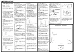
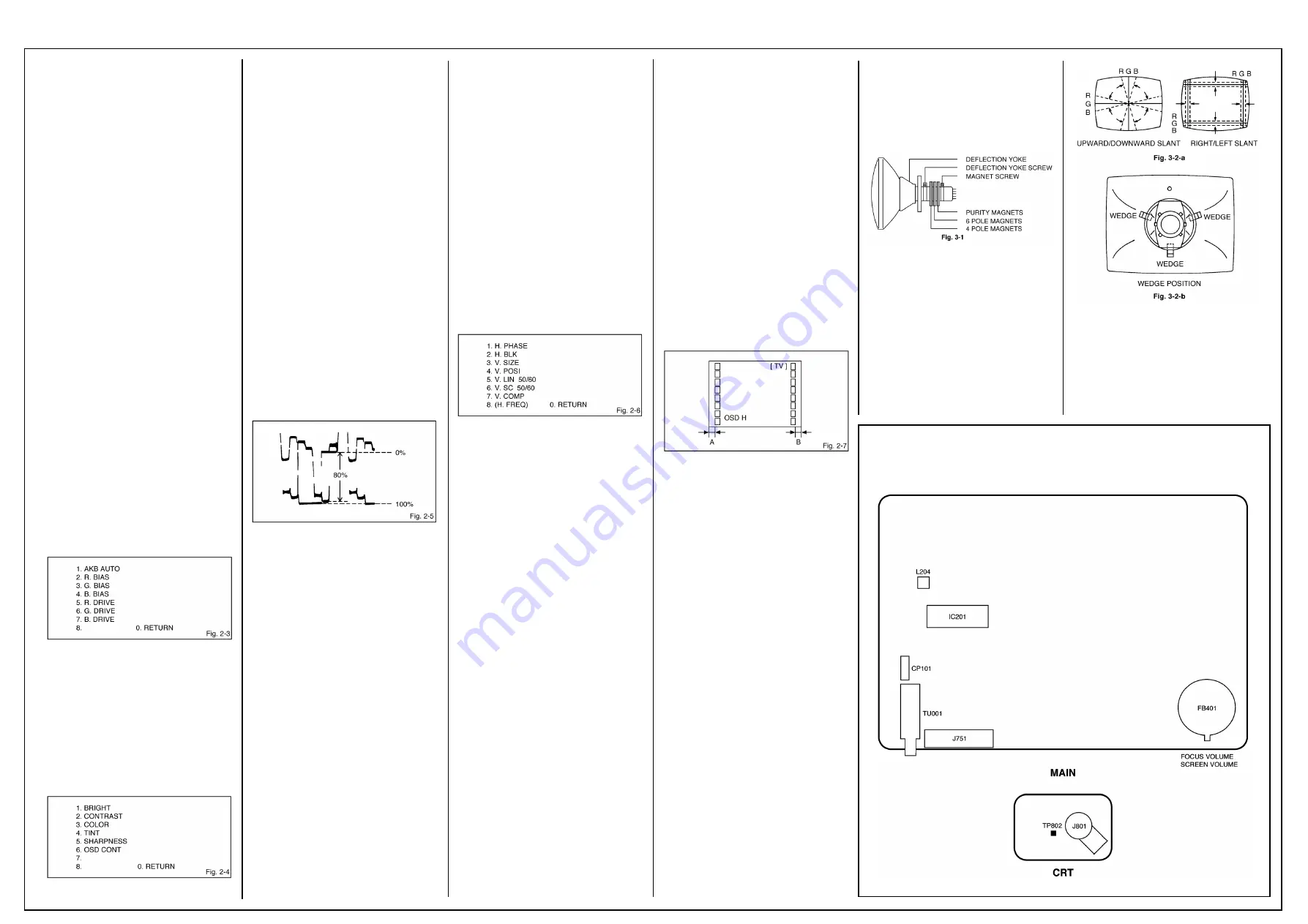
2-2: VCO
1. Receive the color bar pattern.
2. Connect the digital voltmeter to pin 47 of
IC201.
3. Adjust the L204 until the digital voltmeter is
3.5
±
0.05V.
2-3: CUT OFF
1. Place the set with Aging Test for more than 15
minutes.
2. Set condition is AV MODE without signal.
3. Using the remote control, set the brightness
and contrast to normal position.
4. Activate the adjustment mode display of Fig.
2-1 and press the channel button (5) on the
remote control. The Fig. 2-2 appears on the
display.
5. Press the channel button (6) on the remote
control.
6. Adjust the Screen Volume until a dim raster is
obtained.
2-4: FOCUS
1. Using the remote control, set the brightness
and contrast to normal position.
2. Receive the monoscope pattern.
3. Turn the Focus Volume fully counterclockwise
once.
4. Adjust the Focus Volume until picture is
distinct.
2-5: WHITE BALANCE
NOTE:
Adjust after performing adjustments in section 2-3.
1. Receive the color bar pattern.
2. Activate the adjustment mode display of Fig.
2-1 and press the channel button (2) on the
remote control. The Fig. 2-3 appears on the
display.
3. Adjust the adjustment mode display of Fig. 2-
3 until the white color is obtained.
2-6: BRIGHTNESS (TV)
1. Receive the monoscope pattern. (RF Input)
2. Using the remote control, set the brightness
and contrast to normal position.
3. Activate the adjustment mode display of Fig.
2-1 and press the channel button (4) on the
remote control. The Fig. 2-4 appears on the
display.
4. Press the channel button (1) on the remote
control.
5. Press the VOL. UP/DOWN button on the
remote control until the white 0% is starting to
be visible.
2-7: BRIGHTNESS (AV)
1. Receive the monoscope pattern. (Audio Video
Input)
2. Using the remote control, set the brightness
and contrast to normal position.
3. Activate the adjustment mode display of Fig.
2-1 and press the channel button (4) on the
remote control. The Fig. 2-4 appears on the
display.
4. Press the channel button (1) on the remote
control.
5. Press the VOL. UP/DOWN button on the
remote control until the white 0% is starting to
be visible.
2-8: COLOR (TV)
1. Receive the monoscope pattern. (RF Input)
2. Connect the synchro scope to TP802.
3. Using the remote control, set the brightness,
contrast, color and tint to normal position.
4. Activate the adjustment mode display of Fig.
2-1 and press the channel button (4) on the
remote control. The Fig. 2-4 appears on the
display.
5. Press the channel button (3) on the remote
control.
6. Adjust the VOLTS RANGE VARIABLE knob of
the oscilloscope until the range between white
100% and 0% is set to 5 scales on the screen
of the oscilloscope.
7. Press the VOL. UP/DOWN button on the
remote control until the red color level is
adjusted to 80% of the white level. (Refer to
Fig. 2-5)
2-9: COLOR (AV)
1. Receive the monoscope pattern. (Audio Video
Input)
2. Connect the synchro scope to TP802.
3. Using the remote control, set the brightness,
contrast, color and tint to normal position.
4. Activate the adjustment mode display of Fig.
2-1 and press the channel button (4) on the
remote control. The Fig. 2-4 appears on the
display.
5. Press the channel button (3) on the remote
control.
6. Adjust the VOLTS RANGE VARIABLE knob of
the oscilloscope until the range between white
100% and 0% is set to 5 scales on the screen
of the oscilloscope.
7. Press the VOL. UP/DOWN button on the
remote control until the red color level is
adjusted to 80% of the white level. (Refer to
Fig. 2-5)
2-10: CONTRAST
1. Receive the monoscope pattern.
2. Activate the adjustment mode display of Fig.
2-1 and press the channel button (4) on the
remote control. The Fig. 2-4 appears on the
display.
3. Press the channel button (2) on the remote
control.
4. Press the VOL. UP/DOWN button on the
remote control until the bar step is set to the
“20”.
2-11: SHARPNESS
1. Receive the monoscope pattern.
2. Activate the adjustment mode display of Fig.
2-1 and press the channel button (4) on the
remote control. The Fig. 2-4 appears on the
display.
3. Press the channel button (5) on the remote
control.
4. Press the VOL. UP/DOWN button on the
remote control until the bar step is set to the “7”.
2-12: HORIZONTAL PHASE
1. Receive the monoscope pattern.
2. Using the remote control, set the brightness
and contrast to normal position.
3. Activate the adjustment mode display of Fig.
2-1 and press the channel button (1) on the
remote control. The Fig. 2-6 appears on the
display.
4. Press the channel button (1) on the remote
control.
5. Press the VOL. UP/DOWN button on the
remote control until the SHIFT quantity of the
OVER SCAN on right and left becomes
minimum.
2-13: VERTICAL POSITION
1. Receive the monoscope pattern.
2. Using the remote control, set the brightness
and contrast to normal position.
3. Activate the adjustment mode display of Fig.
2-1 and press the channel button (1) on the
remote control. The Fig. 2-6 appears on the
display.
4. Press the channel button (4) on the remote
control.
5. Press the VOL. UP/DOWN button on the
remote control until the horizontal line of the
monoscope comes to approximate center of
the CRT.
2-14: VERTICAL SIZE
1. Receive the crosshatch pattern.
2. Using the remote control, set the brightness
and contrast to normal position.
3. Activate the adjustment mode display of Fig.
2-1 and press the channel button (1) on the
remote control. The Fig. 2-6 appears on the
display.
4. Press the channel button (3) on the remote
control.
5. Press the VOL. UP/DOWN button on the
remote control until the center of crosshatch
is square.
2-15: VERTICAL LINEARITY 50
1. Receive the monoscope pattern.
2. Using the remote control, set the brightness
and contrast to normal position.
3. Activate the adjustment mode display of Fig.
2-1 and press the channel button (1) on the
remote control. The Fig. 2-6 appears on the
display.
4. Press the channel button (5) on the remote
control.
5. Press the VOL. UP/DOWN button on the
remote control until the bar step is set to the
“18”.
2-16: VERTICAL LINEARITY 60
1. Receive the monoscope pattern (NTSC
Signal).
2. Using the remote control, set the brightness
and contrast to normal position.
3. Activate the adjustment mode display of Fig.
2-1 and press the channel button (1) on the
remote control. The Fig. 2-6 appears on the
display.
4. Press the channel button (5) on the remote
control.
5. Press the VOL. UP/DOWN button on the
remote control until the bar step is set to the
“18”.
2-17: OSD HORIZONTAL
1. Using the remote control, set the brightness
and contrast to normal position.
2. Activate the adjustment mode display of Fig.
2-1 and press the channel button (5) on the
remote control. The Fig. 2-2 appears on the
display.
3. Press the channel button (5) on the remote
control.
4. Press the VOL. UP/DOWN button on the
remote control until the difference of A and B
becomes minimum.
PURITY AND CONVERGENCE ADJUST-
MENTS
NOTE
1. Turn the unit on and let it warm up for at least
30 minutes before performing the following
adjustments.
2. Place the CRT surface facing east or west to
reduce the terrestrial magnetism.
3. Turn ON the unit and demagnetize with a
Degauss Coil.
3-1: STATIC CONVERGENCE (ROUGH
ADJUSTMENT)
1. Tighten the screw for the magnet. Refer to the
adjusted CRT for the position. (Refer to Fig.
3-1) If the deflection yoke and magnet are in
one body, untighten the screw for the body.
2. Receive the green raster pattern from the
color bar generator.
3. Slide the deflection yoke until it touches the
funnel side of the CRT.
4. Adjust center of screen to green, with red and
blue on the sides, using the pair of purity
magnets.
5. Switch the color bar generator from the green
raster pattern to the crosshatch pattern.
6. Combine red and blue of the 3 color cross-
hatch pattern on the center of the screen by
adjusting the pair of 4 pole magnets.
7. Combine red/blue (magenta) and green by
adjusting the pair of 6 pole magnets.
8. Adjust the crosshatch pattern to change to
white by repeating steps 6 and 7.
3-2: PURITY
NOTE
Adjust after performing adjustments in section 3-1.
1. Receive the green raster pattern from color
bar generator.
2. Adjust the pair of purity magnets to center the
color on the screen. Adjust the pair of purity
magnets so the color at the ends are equally
wide.
3. Move the deflection yoke backward (to neck
side) slowly, and stop it at the position when
the whole screen is green.
4. Confirm red and blue colors.
5. Adjust the slant of the deflection yoke while
watching the screen, then tighten the fixing
screw.
3-3: STATIC CONVERGENCE
NOTE
Adjust after performing adjustments in section 3-2.
1. Receive the crosshatch pattern from the color
bar generator.
2. Combine red and blue of the 3 color cross-
hatch pattern on the center of the screen by
adjusting the pair of 4 pole magnets.
3. Combine red/blue (magenta) and green by
adjusting the pair of 6 pole magnets.
3-4: DYNAMIC CONVERGENCE
NOTE
Adjust after performing adjustments in section 3-3.
1. Adjust the differences around the screen by
moving the deflection yoke upward/downward
and right/left. (Refer to Fig. 3-2-a)
2. Insert three wedges between the deflection
yoke and CRT funnel to fix the deflection
yoke. (Refer to Fig. 3-2-b)
Component Location Guide


