


Out of Vehicle Test
BATTERY TEST:
1.
Connect the MBT400 Battery Module to the battery to be tested. The green
Ready
LED and the yellow
Activity
LED will blink.
Note:
make sure battery clips make contact with the lead battery post.
2.
Press the ON/OFF button to turn on the remote.
“MATCO MBT400”
will appear momentarily on the display. Press TEST. The display
will show the following screens. Select TEST BATTERY ONLY if testing just the battery. Follow the screen sequence as below. See the
next sections for the starter and charging systems screen sequences.
2
PRIOR TO TESTING
Important:
Use stud or post adapters (provided with the MBT400) when connecting to side mount or Group 31 batteries outside of the vehicle. Or
connect battery clips on the base of threaded stud when testing (see Fig. below). Make sure adapters are properly tightened. Connecting the tester
directly to threaded studs or bolts will result in false readings. When connecting to batteries inside or outside of the vehicle, rock the clips back and
forth to ensure a good connection.
CHECK CONNECTION
may show on the display if a poor connection is detected. Reset clips if necessary.
MENU OPTIONS
SET UP:
Press SET-UP to select language, company info (shop name & address), HPIr-PRINTER
or USB adapter (included), technician name and the date and time. Note: after setting date
and time press SET-UP to save.
VIEW or PRINT:
Press VIEW or PRINT to review last data in memory or print to IR printer or USB adapter.
TEST:
Press TEST to test battery, starter, and charging system. Follow prompts on display. Scroll up/down
and then press enter when desired option is selected
.
Group 31 female
Stud adapters
Side- mount male
post adapters
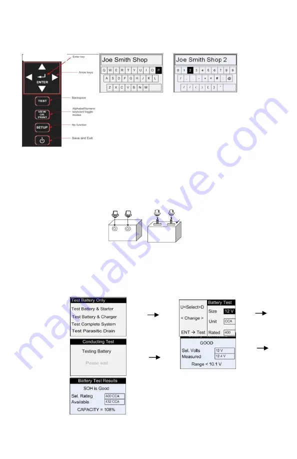
The keypad and the display are used to enter text with the following key assignment:
Figure 2
Figure 3
As seen in Fig. 1, the key functions in this mode have different functions used to enter the text
required.
Use the Arrow keys to navigate the keys on the keyboard layout as shown in Fig. 2 or Fig. 3.
Press ENTER key to add the character selected.
Press Backspace to erase the last character.
Select backslash key (/) to start a new line.
Press the Alphabet/Numeric keyboard toggle modes key to switch between Fig. 2 and Fig. 3
layouts
.
Press Save and Exit key to save and exit
.
Figure 1
(
alphabet mode)


