20
Chapter 3. Hardware Architecture - Evaluation Board
3.4
Jumpers and test connectors
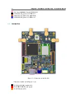
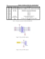
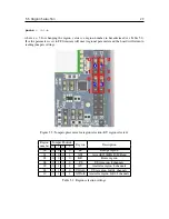
Figure 3.9: Jumpers and test connectors on the Dev Kit.
Components marked on the Figure 3.9 are:
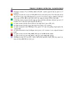
J402 - selection of the source of V3P3 used to power RGB LED and sensors. A jumper
in position 1-2 selects the 3V3 from low power converter (located left), jumper in position 2-3
selects the V3P3_LDO output from integrated LDO of the SoM module
J111, J112 - connect the P1_3 and P0_7 to Grove D1 and D2 lines
J104, J108 - connect the P4_2 and P4_3 to I2C_SDA and I2C_SCL
J105, J109 - connect P1_2 and P2_3 of MatchX SoM to UART_SIM_TX and UART_SIM_RX
of the SIM7000E module
J107 - connects the enable line of the 3.3V LDO that powers SIM7000E ether to EXT_P0_2
(I/O expander) in position 1-2 or to 5V (always on) in position 2-3.
J110 - connects SIM_NRST of the SIM7000E to EXT_P0_1 of the I/O expander


