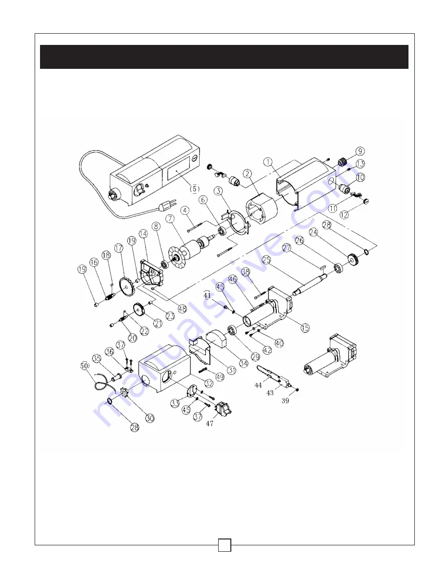
IX. Replacement parts ... continued
25
MASTERCRAFT
®
12 1/2" THICKNESS PLANER
55-5504-2
EXPLODED VIEW OF THE PLANER MOTOR (200 SERIES)
Страница 1: ...12 1 2 THICKNESS PLANER 55 5504 2 Operation and Safety Instructions 310 9902 001 10 02 Toll Free Hotline 1 800 689 9928 Phone 905 792 9769 Fax 905 792 7670...
Страница 2: ...on 9 V Know your planer 11 VI Assembly and adjustments 12 VII Operation 15 VIII Maintenance 18 IX Replacement parts 22 X Warranty 28 12 1 2 THICKNESS PLANER MODEL NUMBER 55 5504 2 MOTOR 120 V 60 Hz 15...
Страница 3: ...se clothing gloves neckties or jewellery rings watches when operating the tool They can get caught and draw you into moving parts ALWAYS wear non slip footwear and tie back long hair 8 WEAR A FACE MAS...
Страница 4: ...laced before use 18 MAKE THE WORKSHOP CHILDPROOF Use padlocks master switches and ALWAYS remove starter keys 19 DO NOT operate the tool if you are under the influence of drugs alcohol or medication th...
Страница 5: ...ner in a dry indoor place protected from rain Keep work area well lit 2 TO AVOID INJURY FROM UNEXPECTED PLANER MOVEMENT Bolt or clamp the planer to a firm level surface where there is plenty of room t...
Страница 6: ...and can cause the wood to kickback Use the right tool Do not force the tool to do a job it is not intended to do 3 INSPECT YOUR WORK AREA Keep the work area clean Cluttered areas and benches invite a...
Страница 7: ...aned 7 PLAN YOUR CUT Small or thin workpieces can kickback when they tip over on the tables or the cutterhead To avoid cutterhead contact or workpiece kickback do not plane workpieces shorter than 14...
Страница 8: ...own or jamming 3 BEFORE FREEING JAMMED MATERIAL Turn the planer OFF Wait for all moving parts to stop Unplug the planer 4 BEFORE LEAVING THE PLANER Turn the planer OFF Unplug the planer Make the works...
Страница 9: ...ation with or without yellow stripes is the equipment grounding conductor If repair or replacement of the electric cord or plug is necessary DO NOT connect the equipment grounding conductor to a live...
Страница 10: ...it Protect your extension cords from sharp objects excessive heat and damp or wet areas Use a separate electrical circuit for your tools This circuit must not be less than a 12 wire and should be prot...
Страница 11: ...orkpiece guides 5 Support infeed roller 6 Mounting holes 7 Measurement scale 8 Carrying handles 9 Cutterhead depth scale 10 Cutterhead depth adjustment handle 11 UP DOWN direction decal 12 Motor brush...
Страница 12: ...ig 1 1 Planer 2 Knife depth alignment tool 3 Hex key 4 Knife alignment wrench 5 Rubber feet 4 6 Hex screw for cutterhead depth adjustment handle 7 Cutterhead depth adjustment handle 8 Spare set of bla...
Страница 13: ...DED UNTIL IT HAS COME TO A COMPLETE STOP Reset button Fig 3 In the event of an overload your planer is equipped with a reset button If the planer experiences an overload turn the power switch to OFF 1...
Страница 14: ...nch or other ridged frame Use the four rubber feet 1 supplied and quality hardware when mounting your planer Install the cutterhead depth adjustment handle 2 onto the planer Use the hex screw provided...
Страница 15: ...oth sides Do not attempt to make a deep cut or a cut deeper than 1 32 0 8 mm Make several passes until the desired thickness is achieved Light cuts create a finer finish Avoid snipes or depressions ma...
Страница 16: ...tting the planing depth Fig 8 9 10 NOTE You must establish the starting point before you attempt to plane the surface The cutterhead contact with the workpiece should only be enough to brush the surfa...
Страница 17: ...the surface of the workpiece This will establish the starting point for the next pass 4 Use the cutterhead depth adjustment scale 3 to determine the desired amount to plane The planer will feed the w...
Страница 18: ...a clean dry rag to clean any build up of debris from underneath cover and the guard Use penetrating oil to clean any moving parts and the depth adjustment screws Apply a light coat of medium weight oi...
Страница 19: ...terhead carrier and planer damage will result 5 While applying light pressure to the knife depth alignment tool tighten anchor screws 12 in counter clockwise direction 13 alternately side to side star...
Страница 20: ...from the spring on the brush Take note of their position in the motor 3 Pull out the brush Inspect the brush and replace if necessary Be sure to replace both brushes even if only one is damaged NOTE A...
Страница 21: ...oilstone is not worn in the centre it must be flat Be sure to remove any burrs on the flat side If the blades are nicked they must be replaced or reground Blades can be reground several times until th...
Страница 22: ...dy 1 106 Screw 4 107 Screw 1 108 Washer 1 109 Link pole 1 110 Handle cover 1 111 Cutterhead handle 1 112 Hex screw 1 113 Pin 4 114 Stopper 4 115 Transport roller 2 116 Blade clalmp 2 117 Blade shaft 1...
Страница 23: ...IX Replacement parts continued MASTERCRAFT 12 1 2 THICKNESS PLANER 55 5504 2 EXPLODED VIEW OF THE PLANER BODY 100 SERIES 23...
Страница 24: ...2 213 Screw 2 214 Gearbox cover 1 215 Gearbox 1 216 Shaft 1 217 Gear 1 218 Key 1 219 Bearing 2 220 Shaft 1 221 Gear 1 222 Key 1 223 Bearing 2 224 Gear 1 225 Shaft 1 226 Bearing 1 227 Key 1 228 C ring...
Страница 25: ...IX Replacement parts continued 25 MASTERCRAFT 12 1 2 THICKNESS PLANER 55 5504 2 EXPLODED VIEW OF THE PLANER MOTOR 200 SERIES...
Страница 26: ...haft 1 309 Link block 4 310 Washer 4 311 Screw 4 312 Roll pole 2 313 Ruler 1 314 Bolt 4 315 Nut 4 316 Work table extension 2 317 Table base 1 318 Washer 4 319 Screw 4 320 Spring pin 4 321 Work table 1...
Страница 27: ...IX Replacement parts continued 27 MASTERCRAFT 12 1 2 THICKNESS PLANER 55 5504 2 EXPLODED VIEW OF THE PLANER BASE 300 SERIES...
Страница 28: ...nship and materials Should this power tool become defective within the stated warranty period return it to the store with proof of purchase and it will be replaced or repaired free of charge This powe...