background image

headline bars

continuation tabs

notes

warnings

15

headline bars

continuation tabs

notes

warnings

MAINTENANCE

MAINTENANCE

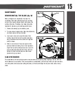
REMOVE/INSTALL THE BLADE

 (fig 10)

After prolonged use, especially in sandy soil 
conditions, the blade will become worn and lose 
some of the original shape, which will reduce the 
cutting efficiency. Therefore, the blade should be 
replaced to ensure a good cutting performance.

1.  Remove the safety key and battery pack. 

2.  Turn the mower upside down. Keep the underbody 

and blade clean and free of debris.

3.  Use a piece of wood to keep the blade from 

turning, loosen the hex bolt counter-clockwise 
using a suitable wrench and remove it together 
with the blade.

4.  Attach a new blade of the same type onto the 

spindle while maintaining the correct alignment. 
Insert the hex bolt on the spindle. Use a piece of 
wood to keep the blade from turning, and then 
tighten the hex bolt clockwise to ensure safe 
operation of your product.

CLEAN THE MOWER

The underside of mower deck should be cleaned after each use as grass clippings, leaves, dirt and 
other debris will accumulate. This accumulation is undesirable, and it will promote rust and corrosion 
on metal parts and reduce the cutting efficiency of the mower. Wipe the mower clean with a damp 
cloth.

fig 10b

fig 10a

Bolt

Blade

Fan

Содержание 060-1350-6

Страница 1: ...model no 060 1350 6 CORDLESS BRUSHLESS 2 IN 1 LAWN MOWER IMPORTANT Read and understand this instruction manual thoroughly before using the product INSTRUCTION MANUAL...

Страница 2: ...headline bars continuation tabs notes warnings...

Страница 3: ...bleshooting 17 Parts List 18 Warranty 21 NOTE If any parts are missing or damaged or if you have any questions please call our toll free helpline at 1 800 689 9928 SAVE THESE INSTRUCTIONS This manual...

Страница 4: ...NS Rated Voltage 40 V d c Deck Size 19 48 cm Cutting Height 1 1 2 to 3 3 8 to 7 6 cm Maximum battery voltage without workload with workload nominal voltage is 18 V Recommend using tool with Mastercraf...

Страница 5: ...ngs in this manual and on the machine and attachments Only allow operators who are responsible trained familiar with the instructions and physically capable to operate the machine Do not operate the m...

Страница 6: ...ery They can be caught in moving parts Use of rubber gloves and footwear is recommended when working outdoors Use safety glasses Always use face or dust mask if operation is dusty Use right appliance...

Страница 7: ...or other small metal objects that can make a connection from one terminal to another Shorting the battery terminals together may cause burns or a fire Under abusive conditions liquid may be ejected f...

Страница 8: ...ction Make turns slowly and gradually ADDITIONAL SAFETY GUIDELINES FOR LAWN MOWER The label on your tool may include the following symbols The symbols and their definitions are as follows V Volts A Am...

Страница 9: ...e Mastercraft battery and chargers listed BATTERY PACK CHARGERS 054 7557 6 054 7553 4 054 3124 0 054 3126 6 054 7559 2 For best results your battery and tool should be stored charged and used in a loc...

Страница 10: ...lertness A fraction of a second of carelessness is enough to cause severe injury PACKAGE CONTENTS Cordless lawn mower 2 cable clamps grass collection bag 2 bolts 2 knobs 2 locking levers 2 washers 2 n...

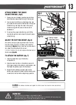
Страница 11: ...lower handle bar face upwards otherwise you will have less space to attach or remove the grass collection bag fig 1b The insert picture shows the outline when looking at the back of the lower handle...

Страница 12: ...NG INSERT fig 4 1 Lift the rear discharge door and insert the mulching insert into the grass outlet of the mower And then release the rear discharge door 2 To remove it lift the rear discharge door an...

Страница 13: ...Do not place the lever out of the five slots fig 6b TO ATTACH THE BATTERY fig 7 1 Open the protective cap of the battery compartment 2 Align the raised portion on the battery pack with the grooves in...

Страница 14: ...witch first pull back the start lever to meet the handle and then release the safety lock off switch to start the machine 3 To stop fully release the start lever The electric brake will stop the blade...

Страница 15: ...lt counter clockwise using a suitable wrench and remove it together with the blade 4 Attach a new blade of the same type onto the spindle while maintaining the correct alignment Insert the hex bolt on...

Страница 16: ...ig 11a CARRY THE MOWER fig 11c After folding the mower it can be carried using the lower handle and the handle on the battery compartment together as shown in fig 11c DO NOT attempt to lift the mower...

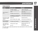
Страница 17: ...ttery compartment Insert the safety key into the slot Mower runs but cutting performance is unsat isfactory Blade is dull Keep the blade sharp Deck or discharge chute is clogging Clean the deck or dis...

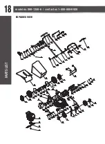
Страница 18: ...headline bars continuation tabs notes warnings headline bars continuation tabs notes warnings model no 060 1350 6 contact us 1 800 689 9928 18 EXPLODED VIEW PARTS LIST...

Страница 19: ...Right Wheel 15 0601350615 Left Front Wheel Cover 47 0601350647 Rear Wheel Cover 16 0601350616 Screw 48 0601350648 Screw 17 0601350617 Torsion Spring Seat 49 0601350649 Bearing Housing 18 0601350618 S...

Страница 20: ...70 0601350670 Elastic Sheet 84 0601350684 Reset Torsion Spring 71 0601350671 Button 85 0601350685 Trigger Cover 72 0601350672 Trigger Block 86 0601350686 Round Cover 73 0601350673 Rocket Switch 87 060...

Страница 21: ...broken or which has become inoperative due to abuse misuse accidental damage neglect or lack of proper installation operation or maintenance as outlined in the applicable owner s manual or operating...

Страница 22: ...may not be transferred Neither the retailer nor the manufacturer shall be liable for any other expense loss or damage including without limitation any indirect incidental consequential or exemplary d...

Отзывы: