model no. 058-8195-2 | contact us 1-800-689-9928
INSTRUCTIONS
YL
B
ME
SS
A
ASSEMBLY INSTRUCTIONS
11
10
WARNING!
When installing the drive roller, the number stamped on the drive roller should face the user.
Push the drive roller onto the drive roller shaft.
5. Pull the drive roller (1) from the drive
roller shaft (2) (fig. D).
1
2
fig. D
MC-588195-05
fig. E
1
2
MC-588195-06
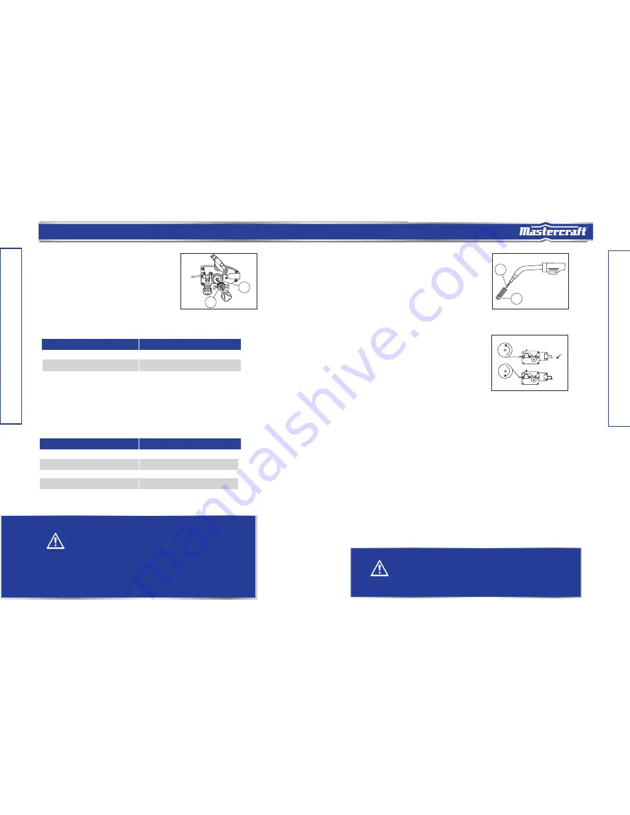
1. Remove the nozzle (1) and contact tip (2)
from the end of the torch assembly
(fig. E).
2. Ensure proper groove on the drive roller
is in place for the wire to be installed.
3. Remove the packaging from the wire
spool and identify the leading end of the
wire secured on the edge of the spool
Do not unhook it at this time.
4. Place the spool on the hub with the
wire passing from the bottom of spool
into the drive mechanism (fig. F).
Note: The welder can use either 4 or 8"
(10 or 20 cm) spool. The 8" (20 cm) spool
requires an adaptor. The wing nut controls
the tension on the spool.
5. Setting the wire spool tension:
a. Turn the wire spool with one hand.
b. Increase the spool tension by tightening the wing nut while turning the spool. Turn the
spool until it slows down.
c. Stop tightening the wing nut. Repeat these steps until proper spool tension is achieved.
Note: If high tension is applied to the wire spool, the wire slips on the drive roller or will
not be able to feed. If less tension is applied, the wire spool unspools itself when the trigger
is released. If the tension is too high or too low, readjust using the wing nut.
6. Disconnect the welder from the power source, and remove the leading end of the wire
from the spool.
7. Cut off any bent portion of the wire using a wire cutter.
8. Loosen the tension adjusting knob holding the drive tension arm in place and lift the
tension arm up off the drive roller.
9. Insert the wire into the inlet guide tube, and feed about 6" (15 cm) of it across the drive
roller and into the torch assembly.
X
MC-588195-07
fig. F
model no. 058-1294-8 | contact us 1-800-689-9928
model no. 058-1294-8 | contact us 1-800-689-9928
model no. 058-1294-8 | contact us 1-800-689-9928
model no. 058-8195-2 | contact us 1-800-689-9928
Note: When installing the drive roller, the number stamped on the drive roller should face the user.
Push the drive roller onto the drive roller shaft.
Based on the wire diameter, select the correct groove using the following table:
6. Reinstall the drive roller cap and lock in place by turning it clockwise. Close the wire drive
compartment.
0.023"
0.023" (0.6 mm)
0.023" (0.6 mm)
0.030" (0.8 mm)
0.030" (0.8 mm)
0.035" (0.9 mm)
0.035" (0.9 mm)
Wire Diameter
Roller Groove
Select the type of wire using the following table:
0.023" (0.6 mm) MIG wire
Yes
0.030" (0.8 mm) MIG wire
Yes
Flux-core wire 0.030" (0.8 mm) Yes
Flux-core wire 0.035" (0.9 mm)
Yes
Wire Type
Availability
WARNING!
• Always switch off the power and unplug the power cord from the AC power
source before installing the wire.
• Remove any wire or wire spool that is rusty.
• Do not weld metal thinner than 18 gauge, as doing so may burn
the metal.
• Before installing, remove any old wire from the MIG gun assem
bly to prevent
the wire from being jammed inside the gun liner.
• Use extreme caution when removing the welding nozzle, as the
contact tip
on the welder is live whenever the torch trigger is pulled.


