background image

headline bars

continuation tabs

notes

warnings

11

headline bars

continuation tabs

notes

warnings

model no. 054-8106-4  |  contact us 1-800-689-9928

10

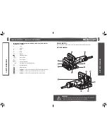
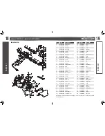
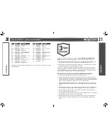
No.

Description

No.

Description

1

Live-tool indicator light

8

Auxiliary handle locking bolt

2

Auxiliary handle

9

Spindle-lock button 

3

Angle-guide plate

10

Height-adjustment locking knob

4

Angle-adjustment locking knob

11

Height indicator

5

Centre mark

12

Cutting-depth stopper

6

Angle scale

13

Dust-exhaust port

7

Blade cover

14

On/off switch

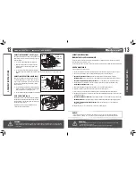
ASSEMBLY INSTRUCTIONS

THE LIVE-TOOL INDICATOR LIGHT

The biscuit joiner is equipped with a live-tool indicator light. When the tool is plugged into an electrical 
supply, the live-tool indicator light will illuminate to remind you that the tool is plugged in. When the tool 
is unplugged, the indicator light will turn off.

ADJUSTING THE DEPTH OF CUT 

(fig 1)

Four different cutting depths can be preset.

Refer to the table below for the correspondence 
between the sizes marked on the cutting depth 
stopper and the biscuit size. 

Fine adjustments to the cutting depth can be made 
by turning the adjusting screw after loosening the hex 
nut. This may become necessary after the blade has 
been re-sharpened a few times.

Set the cutting-depth stopper to match the size below:

Size on cutting-depth stopper

0

10

20

M

Biscuit size

0

10

20

/

Depth of groove

8 mm 

10 mm

12.3 mm

18 mm

ASSEMBL

Y INSTRUCTIONS

WARNING!

•  Never connect the biscuit joiner to a power source when you are assembling parts, 

making adjustments, installing or removing blade, cleaning, or when it is not in use. 

Disconnecting the biscuit joiner will prevent accidental starting, which could cause 

serious personal injury.

WARNING!

•  Do not allow familiarity with the biscuit joiner to cause a lack of alertness. A fraction of a second of 

carelessness is enough to cause severe injury.

FPO

FPO

KEY P

AR

TS DIAGRAM

fig 1

Cutting depth 
adjusting screw

Hex nut

Cutting depth 
stopper

Содержание 054-8106-4

Страница 1: ...model no 054 8106 4 BISCUIT JOINER IMPORTANT Read and understand this instruction manual thoroughly before using the product INSTRUCTION MANUAL...

Страница 2: ...Instructions 13 Maintenance 15 Troubleshooting 17 Parts List 18 Warranty 21 NOTE If any parts are missing or damaged or if you have any questions please call our toll free helpline at 1 800 689 9928 S...

Страница 3: ...utions KNOW YOUR TOOL To operate this tool carefully read this instruction manual and all labels affixed to the biscuit joiner before using Keep this manual available for future reference IMPORTANT Th...

Страница 4: ...ese are connected and properly used Use of these devices can reduce dust related hazards POWER TOOL USE AND CARE Do not force the power tool Use the correct power tool for your application The correct...

Страница 5: ...olts A Amperes Hz Hertz W Watts min Minutes Alternating current Direct current n0 No load speed Class II Construction min Revolutions or reciprocation per minute Grounding terminal BPM Beats per minut...

Страница 6: ...erent cutting depths can be preset Refer to the table below for the correspondence between the sizes marked on the cutting depth stopper and the biscuit size Fine adjustments to the cutting depth can...

Страница 7: ...pencil to mark the centre of the intended biscuit grooves on the workpiece 3 For Corner Joint and T Joint Clamp the vertical workpiece to the workbench fig a1 For Mitre Joint Clamp one workpiece to t...

Страница 8: ...ust and debris from the tool with compressed air or a brush Using compressed air may be the most effective cleaning method Always wear safety goggles when cleaning tools using compressed air LUBRICATI...

Страница 9: ...e the cover Release the spring take out the worn carbon brushes and insert the new ones Reset the spring to fix the carbon brush and secure the cover Make sure the groove on the carbon brush points to...

Страница 10: ...1064043 Front handle 14 5481064014 Gear 44 5481064044 Label 15 5481064015 Front cap 45 5481064045 Switch drawbar 16 5481064016 Spring washer 46 5481064046 Switch button 17 5481064017 Screw 47 54810640...

Страница 11: ...tated warranty period and if covered under this warranty will be repaired or replaced with the same model or one of equal value or specification at our option We will bear the cost of any repair or re...

Страница 12: ...anty applies only to the original purchaser and may not be transferred Neither the retailer nor the manufacturer shall be liable for any other expense loss or damage including without limitation any i...

Отзывы:

Похожие инструкции для 054-8106-4