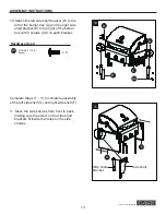
background image

20

Lowes.com/masterforge

COOkINg WITH gAS

a. Hand Assembly:

1.  Make certain the tank valve and all the appliance valves are in the “OFF” position.

2.  When connecting the regulator/burner valve assembly to the tank valve, turn the large plastic 

nut clockwise until it stops.

3. 

Gas will not flow unless the plastic nut is completely connected.

4.  HAND TIGHTEN ONLY.

b. Hand Disassembly:

1.  Make certain the tank valve and all the appliance valves are in the “OFF” position.

2.  Turn the large plastic nut counterclockwise until it is disassembled.

3.  HAND LOOSEN ONLY.

c. Excess Flow Control and low Heat:

The propane regulator assembly incorporates an excess flow device designed to supply the

grill with sufficient gas flow under normal conditions yet control excess gas flow.

Rapid changes in pressure can trigger the excess flow device providing a low flame and low

temperature. If the tank valve is turned open to allow gas flow while a burner valve is open,

the surge of pressure will cause the device to activate. The device will remain closed until the

pressure is equalized. This should occur within 5 seconds.

To ensure this does not cause difficulty in lighting the grill, follow these instructions:

1.  Make sure all burner valves are “OFF”.

2.  Open the tank valve and wait 5 seconds.

3.  Light the burners one at a time following the lighting instructions.

d. Temperature-Activated Shut-Off:

The large plastic nut on the regulator assembly is designed in coordination with a check valve

in the tank valve to shut off the flow of gas when exposed to temperatures between

240-300° F.

In the event of a fire or hose break, one of the safeguards will function to control or stop the

flow of gas from the propane tank. Never attempt to use damaged equipment.

I

mportant: Before the use of a fresh tank of gas, please check leakage around the

connections according to section ‘Checking gas leaks’ and make sure there is no

leakage or vapor accumulation in the cabinet. Make sure all openings around side

walls are not blocked.

Important: Place dust cap on cylinder valve outlet whenever the cylinder is not in use.

Only install the type of dust cap on the cylinder valve outlet that is provided with the

cylinder valve. Other types of caps or plugs may result in leakage of propane.

Содержание 0503231

Страница 1: ...oper installation adjustment alteration service or maintenance can cause injury or property damage Read this instruction manual thoroughly before installing or servicing this equipment WARNING 1 Do no...

Страница 2: ...3 Safety Tips 5 Package Contents 6 Hardware Contents 7 Preparation 8 Assembly Instructions 9 Natural Gas Conversion Instructions 17 Cooking with Gas 19 Operating Instructions 26 Care and Maintenance...

Страница 3: ...electrical supply cords and the fuel supply hose away from heated surfaces 6 Inspect the hoses before each use for excessive abrasion or wear or cuts that may affect safe operation of the grill If the...

Страница 4: ...s which are on the list of substances known by the state of California to cause cancer reproductive harm or other birth defects To reduce exposure to these substances always operate this unit accordin...

Страница 5: ...Never store a propane tank whether full or empty inside your home or living area Before storing your tank make sure that it has been turned to the OFF position Should you store your grill indoors be...

Страница 6: ...6 Lowes com masterforge Package Contents A H G I J K L M N O P Q R S T U B C D E F...

Страница 7: ...Right Side Shelf Bracket 2 F Right Side Shelf 1 G Left Side Shelf 1 H Left Side Shelf Bracket 2 I Drip Tray Support 1 J Safety Tank Ring 1 K Tank Ring Bracket 1 PART DESCRIPTION QUANTITY L Rear Panel...

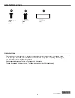
Страница 8: ...ARATION Before beginning assembly of product make sure all parts are present Compare parts with package contents list and hardware contents list If any part is missing or damaged do not attempt to ass...

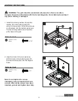
Страница 9: ...12 screws AA When this process is completed turn the bottom panel over The two locking casters Q should be at the back of the grill 2 Align the holes in the rear panel L with the holes in the bottom p...

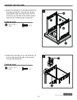
Страница 10: ...panels there are three screws for the rear panel L and four for the bottom panel Insert the four bottom panel screws first Hardware Used AA 3 16 24 x 1 2 in Screw x 14 4 Attach the front beam U to th...

Страница 11: ...ith 2 screws BB as shown 6 Attach the drip tray support I to the front beam U and rear panel L with 4 screws AA as shown 7 Remove the cap and the nut from the igniter M Secure the igniter to the right...

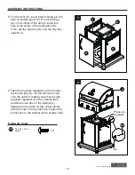
Страница 12: ...the drip tray support I 9 Take the pressure regulator out from under the burner box A Lift the burner box A onto the cabinet making sure that the gas pressure regulator is in the cabinet then position...

Страница 13: ...f the burner box with 2 screws AA on each bracket Hardware Used AA AA 3 16 24 x 1 2 in Screw x 8 Complete Steps 11 13 to complete assembly of the left side shelf G and right side shelf F 11 Move the s...

Страница 14: ...g the side shelves on the brackets and slowly rotate the side shelves 13 Adjust the side shelves until they are aligned with the control box 14 Plug the main burner igniter wires into the sockets in t...

Страница 15: ...TRUCTIONS 15 Place the heat tents B main grids C and warming rack D into the burner box A Remove the battery cap on the igniter M and insert a AA battery CC with the positive end facing outward Replac...

Страница 16: ...NIDAD EN El INTERIOR RETIRE El TANQUE Y D JElO EN El EXTERIOR L G Sourcing Inc P O Box 1535 North Wilkesboro NC 28659 USA Modelo No RT2417S Tipo de gas propano Convertible a Gas Natural Entrada Quemad...

Страница 17: ...ted and discard the rest Follow the conversion instruction provided with the kit Main Burner Conversion 16 Pull off the R pins and take the main burners out Adjust main burners air shutters by looseni...

Страница 18: ...ginal positions Check the sparks before operating the grill Change to 10 ft NG hose 19 Take the regulator off from the manifold and replace it with 10 ft natural gas hose Please make sure the hose is...

Страница 19: ...fety Requirements for Additional Information As shown in Fig 21b it is unsafe to operate the grill if the gas tank is not vertical LP Tank Fig 21a Fig 21b WARNING The Type I connective coupling see Fi...

Страница 20: ...closed until the pressure is equalized This should occur within 5 seconds To ensure this does not cause difficulty in lighting the grill follow these instructions 1 Make sure all burner valves are OFF...

Отзывы: