2
110522-3
Cooler Installation
Installing Casters
Note:
The installation kit includes (2) swivel casters with brake, (2)
swivel casters without brake, (16) tinnerman nuts and (16) 1/4-20
x 1/2 screws.
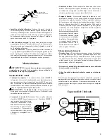
• Place the unit on its side. Place the tinnerman nuts on the caster
bracket on the bottom pan as shown in fi gure 1.
• Attach the casters to the brackets with the screws provided.
Operation
Settings
•
Pump setting.
The rotary switch has 6 settings. The “Pump”
setting will operate the pump without the blower. For best results
turn the switch to “Pump” for a few minutes to wet the pads before
operating the fan.
•
High and low cool settings.
The “High Cool” and “Low Cool” set-
tings operate both the pump and the blower. Turn the unit to “Low
Cool” when possible. This lower speed allows the air to stay longer
in the wet pads and therefore increases it’s cooling effi ciency.
•
High and low vent settings.
The “High Vent” and “Low Vent”
settings operate the blower without the pump. This is useful on
cool nights or at times when just a fan is desired.
Exhaust Air
If the unit is used in an enclosed area, open windows or doors to ensure
adequate exhaust. Without an outlet to exhaust the air, humidity will
build up in the enclosed space and the unit will not cool adequately.
Connecting Water
•
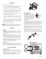
Install drain assembly.
Place the
nipple through the hole in the pan,
with the rubber washer between the
pan and the head of the drain nipple
(Fig. 2). Thread nut onto nipple and
draw up tight against bottom of pan.
Thread the drain cap to the nipple and
tighten water tight.
•
Install fl oat valve.
Refer to fi gure 3. Install the valve in the pro-
vided hole in the corner post using the provided washer and nut.
Install the included garden hose adapter to the fl oat as shown if
attaching a garden hose to the unit. A 1/4 inch water line may also
be used to supply a continuous amount of water to the unit.
•
Fill pan with water.
You may fi ll the pan manually for up to 3
hours of cooling. For automatic fi lling you may attach a garden
hose to the garden hose adapter or a 1/4 inch water line to the fl oat
valve.
Note: Do Not Overfi ll.
Fill water to a maximum height of 2 1/2
inches (approximately 1 inch from the top of the bottom pan). If
using a garden hose, the fl oat will need to be adjusted to maintain
this water level. This can be accomplished by bending the fl oat
rod.
Fig. 1
Bottom Pan
Nipple
Rubber Washer
Nut
Drain Cap
Fig. 2
Float Body
Float Rod
Washer
Nut
Garden Hose
Adapter
Fig. 3
Wiring Diagrams
White-Com.
Black-Hi
Black
Blower
Motor
Pump
Motor
Red-Lo
White-Com.
Green-Ground
Green
Switch
A
B
1
2
3
4
Ribbed-Com.
Plain
Green
Safety Rules
1. Read these instructions carefully.
2. Unit must be in the
Off Position
and
Unplugged
from power
receptacle when installing or performing any maintenance.
3. This cooler will run on 120 volt A.C., 60 Hz (cycle) current only.
4. Motor and pump are grounded and have an automatic thermal
overload switch which will shut motor off if it overheats. The
motor will restart automatically when it cools down.
5. Pump receptacle is for grounded evaporative cooler pump only.
Do not plug anything else into receptacle.
6. Do Not operate any fan with a damaged cord or plug. Discard fan
or return to an authorized service facility for examination and/or
repair.
7. Do Not run cord under carpeting. Do Not cover cord with throw
rugs, runners or similar coverings. Do Not route cord under
furniture or appliances. Arrange cord away from traffi c area and
where it will not be tripped over.
8. Use only in GFCI protected receptacles.
WARNING
: To reduce the risk of fi re or electric shock, do not
use this fan with any “solid-state fan speed control device.”


