5.
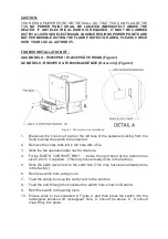
Remove switch from wiring loom.
6.
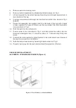
Remove bottom heatshield by unfastening 6 black screws ref. Fig 3.
7.
Lift and support the fan whilst feeding the wiring loom through square hole in
rear channel of the leg.
8.
Continue to feed the end through the knockout fan switch hole, shown in Fig 3
Detail B.
9.
Fasten fan assembly into position and fit to the back of the leg with 4 black
screws supplied. For ease of fitment, put the top screws first, then the bottom
ones as shown in Fig 3.
10.
Refit the switch to the wiring loom.
11.
Ensure wires to be connected in Fig 2, and then press the switch into the
knockout rectangular hole, ‘II’ should be above ‘0’. It should snap firmly into
place.
12.
Connect the loose earth wire (green/yellow) to the earth tab at rear channel of
the leg, this is a push
-
on connection.
13.
Refit the bottom heat shield by fastening 6 black screws ref. Fig 3.
14.
Plug the 3
-
pin plug into the wall outlet and test the operation of the fan.
FAN BOX INSTALLATION OF :
AUS MODEL
-
R5000 WOOD STACKER (Figure 4)
Figure 4. Wood Stacker version installation


