masosine Certa Plus Скачать руководство пользователя страница 20

Plug all other possible connections on the frame, using the
threaded plugs supplied with the pump (see "Parts lists" on
page 43 
for the part numbers). The other connections are
intended for use with different orientations of the pump's
nozzles (see "Possible pump orientations" on page 17).

14.2 Static flushing device

Before commissioning, fill the flushing device (if supplied) with a suitable flushing fluid, depending on the
product being pumped. Fill the sight glass with flushing fluid until the fluid level is just below the bend in
the outlet pipe.

Fitting the static flushing device

The static flushing device can be fitted to a Certa Plus pump with a flush ring or a double mechanical
seal. See also "Assembling the pump head" on page 34.

The connection with the vent pipe must be connected to the highest flush port.

l

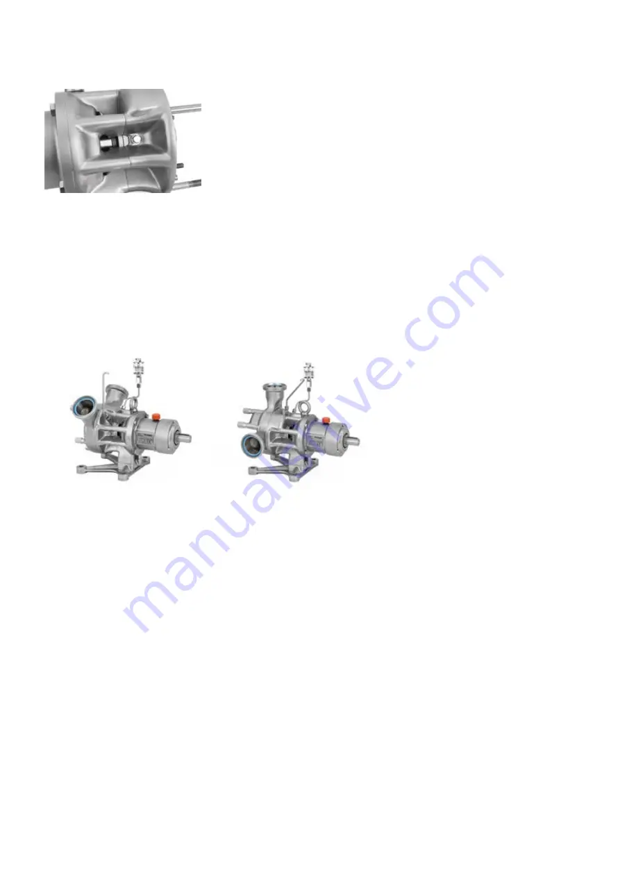
For a 10/2 nozzle orientation this is the flush port located 45° off the vertical axis.

l

For all other nozzle orientations this is the flush port on top of the pump.

The connection with the sight glass must be fitted to the flush port which is offset by 45° from the
vertical axis.

Remove the threaded plug of the required flush port by using a 10mm Socket with extension.

Apply an appropriate sealing material (e.g. Teflon tape) to both threads of the double nipples and fit
them to the flush ports using a 14mm spanner.

Connect the sight glass and the vent pipe with the installed connectors using two 14mm spanners to
tighten them.

Check if the reservoir and the vent pipe are at the same height and close all flush ports.

Removing the static flushing device

The static flushing device must be emptied and removed before disassembling the pump. To do this,
open the flush port at the lowest point of the pump.

After the flushing device has been emptied, reverse the sequence of operations described above to
remove it.

14.3 Fitting a flush ring

See "Assembling the flush ring of a single mechanical seal system" on page 37.

20

m-certa-plus-en-02

Содержание Certa Plus

Страница 1: ... devices 7 9 9 Dangers due to hazardous pumped material 7 9 10 Dangers due to electrical energy 7 9 11 Dangers due to hydraulic energy 7 9 12 Special danger points 8 9 13 Constructional changes to the machine 8 9 14 Noise 8 9 15 Limit values for the pump 9 9 16 Maintenance and repair 9 9 17 Cleaning the pump 10 9 18 Faults 10 10 Pump specifications 11 10 1 Standards 11 10 2 Dimensions 12 Dimension...

Страница 2: ...h the shim ring 31 19 6 Checking the X Dimension 32 19 7 Assembling the front mechanical seal 32 19 8 Assembling the pump head 34 19 9 Assembling the flush ring of a single mechanical seal system 37 19 10 Assembling the back seal in a double mechanical seal system 37 20 Tightening torques 41 21 Parts lists 43 21 1 Rotor types 43 21 2 Pumps 44 21 3 Single mechanical seal 50 21 4 Flush ring 51 21 5 ...

Страница 3: ...isation of the laws of the Member States relating to electromagnetic compatibility recast Official Journal of the EU L 96 79 of 29 03 2014 Directive 2014 35 EU was complied with in accordance with Annex I No 1 5 1 MRL 2006 42 EC with regard to its protection objectives According to Directive 2014 68 EU Artikel 4 3 the above mentioned manufacturer certifies in accordance with the applicable good en...

Страница 4: ...s or subcontractors MasoSine grants no implicit warranties on the suitability of the products described for a certain application MasoSine accepts no liability for errors contained in this documentation or consequential damage occurring due to the design performance and the use of this documentation MasoSine s General sales and delivery conditions contain full details These are available to the pu...

Страница 5: ...ivation for chemical attack and replace them if necessary 5 Information for returning pumps In compliance with the regulations in your area concerning the control of substances hazardous to health you are required to declare the substances which have been in contact with product s you return to MasoSine or its distributors Failure to do so will cause delays Please ensure that you email us this inf...

Страница 6: ...mped fluid is displaced As a filled chamber rotates it contracts closes and discharges its contents At the same time the opposite chamber opens by the same fraction of a millimetre to draw in more fluid The result is a pump free of pulsation The gate works as a seal between the pressure side and the suction side of the pump It prevents an equalisation of the pressure created by the rotor stopping ...

Страница 7: ...immediately 9 7 Safety measures in normal operation Operate the machine only if all protective devices are functioning Before switching the machine on make sure that no one can be endangered when the machine starts At least once per shift inspect the machine for damage and for proper functioning of the safety devices 9 8 Protective devices All protective devices must be attached correctly and func...

Страница 8: ...nversion measures require the written confirmation of Watson Marlow GmbH MasoSine Division Replace machine parts which are not in perfect condition immediately Use only original spare and wearing parts Parts that are not obtained from MasoSine are not guaranteed to be designed and manufactured in compliance with load and safety requirements The warranty is invalid if genuine spare parts from MasoS...

Страница 9: ...erating personnel before starting maintenance and repair work Protect all plant parts and operating media connected before and after the machine such as compressed air and hydraulics against unintentional start up In all maintenance inspection and repair work switch the machine off and secure the main switch against unintentional start up Secure larger assemblies carefully to lifting gear Check lo...

Страница 10: ...maintenance Bearing frame Expert Change bearings Contact Watson Marlow MasoSine for assistance Points to observe during maintenance l Clean all accessible seal grooves before assembling l All accessible surfaces threads and dismantled components shall be cleaned with a suitable cleaning agent l Clean the thread in the shaft and on the locking nut before installing the lock nut again to prevent the...

Страница 11: ...he serial number also appears on the technical datasheet An example name plate is shown below the abbreviations on the label are as follows Pm maximum pressure max maximum speed s n serial number 10 1 Standards Standards applicable to the pump connected to a drive See Declaration of conformity on page 3 or supplied with the pump m certa plus en 02 11 ...

Страница 12: ...P100 5 47 3 35 0 39 4 72 5 31 Ø0 47 5 63 2 24 10 43 1 97 3 74 5 08 Ø1 10 0 31 1 22 P200 6 10 3 92 0 39 4 72 5 31 Ø0 47 6 59 3 21 11 75 1 97 4 31 5 71 Ø1 10 0 31 1 22 P250 7 54 5 45 0 45 7 48 6 89 Ø0 67 8 62 3 31 13 86 1 97 5 91 7 08 Ø1 10 0 31 1 22 P300 9 35 6 00 0 68 9 84 8 46 Ø0 79 11 22 6 06 17 93 3 15 6 69 8 66 Ø1 97 0 55 2 11 P400 12 74 6 65 1 22 10 49 10 00 Ø0 83 11 85 6 65 20 22 3 03 7 87 1...

Страница 13: ...The pump must be suspended correctly for transport If using a crane or fork lift truck the ropes or belts must be sufficiently dimensioned If the pump is transported with a lift truck or fork lift truck note that the unit s centre point is not necessarily the centre of gravity m certa plus en 02 13 ...

Страница 14: ...irect as possible though ideally not shorter than one metre and follow the straightest route Use bends of large radius at least four times the pipe diameter Ensure that connecting pipework and fittings are suitably rated to handle the predicted pipeline pressure Avoid pipe reducers and lengths of smaller bore pipe than the pumphead section particularly in pipelines on the suction side Any valves i...

Страница 15: ...greed in the purchase order and listed in the technical data sheet is not possible MasoSine pumps normally run with such a low resonant frequency that no damage results However particularly when running with inverters certain frequencies can cause interference vibrations which must be avoided It is important during commissioning to ascertain whether such vibrations exist and to define them so that...

Страница 16: ... peaks up to several thousand bar These pressure peaks can cause material erosion and are noisy To identify cavitation If the pump is very noisy and vibrates vigorously along with the pipe system attached to the pump cavitation is likely to be the cause To avoid or remove cavitation Increasing the inlet pressure on the suction side installing a larger diameter or shorter inlet pipe or slowing the ...

Страница 17: ...ote According to EHEDG regulations the pump head should always be completely self draining In a standard installation this can only be assured in the 02 04 or 08 10 nozzle position Changing the pump orientation See Disassembling the support Changing the nozzle orientation on page 30 for details about changing the pump orientation 12 5 Connecting to a power supply The motor must be connected accord...

Страница 18: ...luid with the fluid level above the rotor see diagram This can be done manually through a side channel of your system s pipework or by using a vacuum device where very viscous fluids are to be pumped contact MasoSine for further information The need to prime can be avoided by leaving product in the pump after it is stopped by leaving CIP or SIP fluid in the pump after cleaning Before start up make...

Страница 19: ...tmosphere l The single mechanical seal should be flushed without pressure the flushing fluid should be allowed to drain from the system without pressure The double mechanical seal can be used pressureless or alternatively with an overpressure l Fill the pump with liquid to prevent it from running dry possibly via a separate intake valve connected to the suction or pressure pipe l If your pump is s...

Страница 20: ... 45 off the vertical axis l For all other nozzle orientations this is the flush port on top of the pump The connection with the sight glass must be fitted to the flush port which is offset by 45 from the vertical axis Remove the threaded plug of the required flush port by using a 10mm Socket with extension Apply an appropriate sealing material e g Teflon tape to both threads of the double nipples ...

Страница 21: ...l Suitable cleaning fluids for the CIP process may include concentrations below 1 of additives They may be o Sodium hydroxide in distilled water o Nitric acid in distilled water o Phosphoric acid in distilled water l CIP cleaning can be carried out between 60C 140F and 100C 212F depending on customer needs l Cleaning should be done at maximum pump speed to achieve a good cleaning result l It is re...

Страница 22: ...tain fibres a sufficient cleaning cannot always be ensured by CIP In this case a manual cleaning procedure is recommended Determine the pump cleaning schedule on site for materials being processed and plant maintenance schedule Principally MasoSine Certa Plus series pumps do not require manual cleaning if CIP clean in place is performed after operation To disassemble the pump head see Disassemblin...

Страница 23: ...il vent valve A l Check the oil level in viewing glass at B Do not allow the level to fall below the viewing glass centre line Note When a new pump is supplied it is filled as standard with Klüberoil 4 UH 1 220 N lubrication oil for the food and pharmaceutical industries which is suitable for process temperatures between 30C 22F and 120C 248F Filling volumes Volumes are shown in litres P100 Approx...

Страница 24: ...sition of the connections varies depending on the model A possible backpressure should not exceed 1bar 15psi The minimum flow required for the heating cooling option is 0 2l min or 0 05gpm Note Most pump sizes can be retro fitted to allow heating and cooling refer to table below Note The heating or cooling temperature must stay within the temperature limits of the pump These can be found in Limit ...

Страница 25: ...k housing Housing seal not installed or wrongly installed Install housing O ring correctly or replace Housing seal defective Install housing O ring correctly or replace Pump is blocked Foreign body in the pump Remove foreign body examine pump for damage Power supply interrupted Check electrical installation and fuses check drive Defect in the drive Separate the coupling and turn the pump by hand t...

Страница 26: ...o support the weight of the pump during disassembly and assembly to avoid personal injury Removing the static flushing device If the flushing device has been fitted it must be emptied and removed before disassembling the pump For details see Static flushing device on page 20 19 1 Disassembling the pump Removing the front housing l Make sure the pump is secured to prevent it from tilting l Unscrew ...

Страница 27: ...ng the socket adapter turning it counter clockwise for part code see Tools on page 56 High torque required Use appropriate tool An O ring seal keeps the disc spring of the locking screw in place The component parts of the locking screw The quantity of the component parts can vary between the different sizes see Parts lists on page 43 l Remove the blocking tool Removing the rotor and gate l Pull th...

Страница 28: ...oving the rotor to ensure the seal faces are not damaged The seal faces are brittle To re assemble the pump refer to the assembly instructions below starting with section Assembling the support Centering the rotor with the shim ring on page 31 28 m certa plus en 02 ...

Страница 29: ...ot necessary for regular maintenance Removing the seal system l Carefully remove the back seal face from the mechanical seal system and store it safely The seal face with O ring at the outer diameter which is installed in the pump housing Removing the spring assembly l Remove the spring assembly from the back housing m certa plus en 02 29 ...

Страница 30: ...mp The assembly procedure of the middle housing is shown in section Assembling the pump head on page 34 19 4 Disassembling the support Changing the nozzle orientation Disassembling the support unit l Undo the screws on the support at the back of the housing by turning them counter clockwise with a wrench l Carefully pull out the support unit Changing the nozzle orientation l Undo the screws by tur...

Страница 31: ...ith the segments on the end shield l Tighten the screws by turning clockwise 19 5 Assembling the support Centering the rotor with the shim ring l Place the shim ring at the flange of the support l Insert the support unit into the end shield l Tighten the screws on the support at the back of the housing by turning them clockwise with a wrench m certa plus en 02 31 ...

Страница 32: ...ake out the support unit to get access to the shim ring Peel off as many layers as needed to get the correct X Dimension Each layer is 0 05mm thick P100 0 10 0 05 mm 0 004 0 002 in P200 0 12 0 05 mm 0 005 0 002 in P250 0 15 0 05 mm 0 006 0 002 in P300 0 15 0 05 mm 0 006 0 002 in P400 0 15 0 05 mm 0 006 0 002 in 19 7 Assembling the front mechanical seal The arrows show the two notches in the housin...

Страница 33: ... l Assemble the seal face in the housing Make sure the small pin fits into the notch on the seal face The pins need to match the according notches to prevent the part from rotating l The seal face is in place once a catching can be noticed and the seal face stays in place l A higher force might be required Check for compression of the spring assembly Fitting the rotor seal system The seal face for...

Страница 34: ...ar of the middle housing You do not need to disassemble the middle housing to change for example the Gate or the mechanical seal system This is only explained for the sake of completeness l Locate the middle housing over the threaded pins l Make sure you align the slot where the gate is placed with the same slot in the back housing l Tighten the nuts clockwise to hold the middle housing in place M...

Страница 35: ...ocking Screw with cup side pointing away from Locking Screw head Failure to do so will result in the Locking Screw vibrating loose Cup side of disc spring 1x Disc Spring P100 P250 2x Disc Spring P300 P400 Use the appropriate torque value see Tightening torques on page 41 l Fasten the locking screw with the socket adapter You may need to lock the shaft to prevent it from turning using the blocking ...

Страница 36: ...ousing l Fit the seal in the front of the middle housing l Attach the front housing Make sure you align the channel correctly over the gate l Tighten the cap nuts by turning them clockwise with a wrench 36 m certa plus en 02 ...

Страница 37: ...m The picture shows the foot plate turned through 180 to prevent the pump from falling because the housing is not attached Flush ring completely assembled with lip seal and O Ring The flush ring in the back of the end shield This is used with the single mechanical seal system A lip seal is placed in the ring in the same way as a flush ring for a flush system l Put the O ring in place as shown 19 1...

Страница 38: ... the according notches to prevent the part from rotating l Press the seal face in place into the seal holder l Fit the O ring in the notch on the inner diameter of the seal holder The red arrow shows the O Ring in place l Put the assembled seal system on the shaft of the disassembled support unit The pins need to match the according notches to prevent the part from rotating The pin correctly fitte...

Страница 39: ...nto the notches arrowed The pins need to match the according notches to prevent the part from rotating For instructions on assembling the parts in the spring assembly see Assembling the front mechanical seal on page 32 The spring assembly correctly assembled in the rear of the back housing l Put the O ring on the outer diameter of the seal face l Fit the seal face together with the O Ring in the r...

Страница 40: ... orientation See Possible pump orientations on page 17 l Tighten the screws by turning them clockwise The first part of the back seal system installed in the pump back housing l Carefully assemble the support unit with the installed seal face l Tighten the screws on the support at the back of the housing by turning them clockwise using a wrench View into the open area showing the back seal system ...

Страница 41: ...lb ft End shield Support M8 A2 70 DIN 931 16Nm 12 lb ft End shield Threaded plug R 1 4 DIN 908 25Nm 18 5 lb ft Back housing End shield M6 A2 70 DIN 912 7Nm 5 lb ft Shaft Locking screw M10x1 45Nm 33 lb ft Front housing Cap nut SW22 35Nm 26 lb ft Mechanical seal Set screw M4 SW3 P250 Adjoining parts Screw type Torque Cover for bearing Support M6 A2 70 DIN 931 7Nm 5 lb ft End shield Support M10 A2 70...

Страница 42: ...0Nm 88 5 lb ft Front housing Cap nut SW22 45Nm 33 lb ft Mechanical seal Set screw M5 SW4 P400 Adjoining parts Screw type Torque Cover for bearing Support M6 A2 70 DIN 931 7Nm 5 lb ft End shield Support M12 A2 70 DIN 931 56Nm 41 5 lb ft End shield Threaded plug R 1 4 DIN 908 25Nm 18 5 lb ft Back housing End shield M10 A2 70 DIN 912 33Nm 24 5 lb ft Shaft Locking screw M20x1 5 120Nm 88 5 lb ft Front ...

Страница 43: ... for Gate Material 47 PTFE 59USP Peek nature LSG 88 PTFE Elastomers e g for O rings Material 82 EPDM 84 FKM 21 1 Rotor types Standard shape rotor Hi Endurance Round shape rotor Lo Shear Product comparison Standard shape rotor Hi Endurance Round shape rotor Lo Shear Example part number Pxxx 0100 xx Pxxx 0120 xx Pump performance with low viscous media against high pressure Good Medium Wear resistanc...

Страница 44: ...21 2 Pumps 14 13 25 8 12 11 9 28 7 21 20 10 32 17 29 6 48 49 35 16 18 40 41 3 1 23 15 24 22 27 26 44 30 39 38 31 5 37 4 36 42 X 2 46 45 19 44 m certa plus en 02 ...

Страница 45: ...Tapered roller bearing 26 1 P100 2000 12 Drain plug 27 1 P100 3800 51 Oil sight glass 28 1 P100 5000 25 Snap ring 29 8 P100 1900 12 Hexagon socket head cap screw 30 1 P100 1300 12 End shield 31 1 P100 1301 12 Foot plate 32 1 P100 1402 12 Cover Plate 33 Not required 34 Not required 35 3 P100 1800 12 Stud 36 2 P100 1750 Seal pump housing 37 3 P100 1800 12 Stud Number Quantity Part code Item 38 2 P10...

Страница 46: ... 2600 25 Tapered roller bearing 26 1 P200 2000 12 Drain plug 27 1 P200 3800 51 Oil sight glass 28 1 P200 5000 25 Snap ring 29 8 P200 1900 12 Hexagon socket head cap screw 30 1 P200 1300 12 End shield 31 1 P200 1301 12 Foot plate 32 Not required 33 Not required 34 Not required 35 2 P200 1850 12 Stud 36 2 P200 1750 Seal pump housing 37 3 P200 1800 12 Stud Number Quantity Part code Item 38 2 P200 501...

Страница 47: ...P250 2600 25 Tapered roller bearing 26 1 P250 2000 12 Drain plug 27 1 P250 3800 51 Oil sight glass 28 1 P250 5000 25 Snap ring 29 8 P250 1900 12 Hexagon socket head cap screw 30 1 P250 1300 12 End shield 31 1 P250 1301 12 Foot plate 32 Not required 33 Not required 34 Not required 35 2 P250 1850 12 Stud 36 2 P250 1750 Seal pump housing 37 3 P250 1800 12 Stud Number Quantity Part code Item 38 2 P250...

Страница 48: ... 25 1 P300 2600 25 Tapered roller bearing 26 1 P300 2000 12 Drain plug 27 1 P300 3800 51 Oil sight glass 28 Not required 29 8 P300 1900 12 Hexagon socket head cap screw 30 1 P300 1300 12 End shield 31 1 P300 1301 12 Foot plate 32 Not required 33 Not required 34 Not required 35 2 P300 1850 12 Stud 36 2 P300 1750 Seal pump housing 37 3 P300 1800 12 Stud Number Quantity Part code Item 38 2 P300 5010 ...

Страница 49: ...0 2600 25 Tapered roller bearing 26 1 P400 2000 12 Drain plug 27 1 P400 3800 51 Oil sight glass 28 1 P400 5000 25 Snap ring 29 8 P400 1900 12 Hexagon socket head cap screw 30 1 P400 1300 12 End shield 31 1 P400 1301 12 Foot plate 32 Not required 33 Not required 34 Not required 35 2 P400 1850 12 Stud 36 2 P400 1750 Seal pump housing 37 3 P400 1800 12 Stud Number Quantity Part code Item 38 2 P400 50...

Страница 50: ...0 5246 O ring 69 1 P200 5220 10 Spring assembly Included in wearing kit Wearing kit mechanical seal P200 0660 See Wearing kit above P250 0640 Number Quantity Part code Item 60 1 P250 5240 Dynamic face with cup 61 1 P250 5245 41 Static face 63 1 P250 5246 O ring 69 1 P250 5220 10 Spring assembly Included in wearing kit Wearing kit mechanical seal P250 0660 See Wearing kit above P300 0640 Number Qua...

Страница 51: ... 82 1 P200 2340 80 Lip seal X 1 See P200 0640 on the previous page Sealing system P250 Number Quantity Part code Item 80 1 P250 1308 10 Distance ring 81 1 P250 1755 80 O ring 82 1 P250 2340 80 Lip seal X 1 See P250 0640 on the previous page Sealing system P300 Number Quantity Part code Item 80 1 P300 1308 10 Distance ring 81 1 P300 1755 80 O ring 82 1 P300 2340 80 Lip seal X 1 See P300 0640 on the...

Страница 52: ... 41 Dynamic face 72 1 P100 5345 41 Static face 74 1 P100 5311 O ring 75 1 P100 5341 O ring 76 1 P100 5346 O ring 79 1 P100 5320 10 Spring assembly X 1 See P100 0640 on page 50 Sealing system P200 Number Quantity Part code Item 70 1 P200 5310 10 Dynamic ring holder 71 1 P200 5340 41 Dynamic face 72 1 P200 5345 41 Static face 74 1 P200 5311 O ring 75 1 P200 5341 O ring 76 1 P200 5346 O ring 79 1 P20...

Страница 53: ...Dynamic ring holder 71 1 P300 5340 41 Dynamic face 72 1 P300 5345 41 Static face 74 1 P300 5311 O ring 75 1 P300 5341 O ring 76 1 P300 5346 O ring 79 1 P300 5320 10 Spring assembly X 1 See P300 0640 on page 50 Sealing system P400 Number Quantity Part code Item 70 1 P400 5310 10 Dynamic ring holder 71 1 P400 5340 41 Dynamic face 72 1 P400 5345 41 Static face 74 1 P400 5311 O ring 75 1 P400 5341 O r...

Страница 54: ...Item 90 1 80 0015 95 Sight glass 91 1 C200 0171 10 Flush pipe 92 1 C200 0173 10 Vent pipe 93 2 80 6009 10 Double nipple 94 2 80 6020 10 Connecting piece 95 1 80 6021 10 Connecting piece P250 Number Quantity Part code Item 90 1 80 0015 95 Sight glass 91 1 C250 0171 10 Flush pipe 92 1 C250 0173 10 Vent pipe 93 2 80 6009 10 Double nipple 94 2 80 6020 10 Connecting piece 95 1 80 6021 10 Connecting pie...

Страница 55: ...73 10 Vent pipe 93 2 80 6009 10 Double nipple 94 2 80 6020 10 Connecting piece 95 1 80 6021 10 Connecting piece 21 7 Dynamic flush system P100 Number Quantity Part code Item 99 2 P100 0504 10 Flush connection P200 Number Quantity Part code Item 99 2 P200 0504 10 Flush connection P250 Number Quantity Part code Item 99 2 P250 0504 10 Flush connection P300 Number Quantity Part code Item 99 2 P300 050...

Страница 56: ...king tool P300 1 TL P300 010 31 Blocking tool P400 1 TL P400 010 31 Blocking tool Socket adapter Pump Size Quantity Part code Item P100 1 TL P100 003 10 Socket adapter P200 1 TL P200 003 10 Socket adapter P250 1 TL P250 003 10 Socket adapter P300 1 TL P300 003 10 Socket adapter P400 1 TL P400 003 10 Socket adapter 56 m certa plus en 02 21 8 Tools ...

Страница 57: ...ide for atmospheric side contact MasoSine Pxxx 0660 95 Wearing Kit Mechanical Seal Product Side SiC SiC FKM Pxxx 0660 95EP Wearing Kit Mechanical Seal Product Side SiC SiC EPDM Pxxx 0660 97 Wearing Kit Mechanical Seal Product Side SiC CA FKM Pxxx 0660 97EP Wearing Kit Mechanical Seal Product Side SiC CA EPDM Wearing kit Number Quantity Part code Item 60 1 Pxxx 5240 88 Dynamic face with cup 61 1 Px...

Страница 58: ...arts Part Number Location P100 0200 13 P200 0200 13 P250 0200 13 P300 0200 13 P400 0200 13 P100 0300 13 P200 0300 13 P250 0300 13 P300 0300 13 P400 0300 13 P100 0350 13 P200 0350 13 P250 0350 13 P300 0350 13 P400 0350 13 58 m certa plus en 02 ...

Страница 59: ...t Number Location P100 0100 P200 0100 P250 0100 P300 0100 P400 0100 P100 1100 13 P200 1100 13 P250 1100 13 P300 1100 13 P400 1100 13 P100 0400 P200 0400 P250 0400 P300 0400 P400 0400 m certa plus en 02 59 ...

Страница 60: ...son Marlow Limited Fluid Technology Group accepts no liability for any errors it contains and reserves the right to alter specifications without notice WARNING This product is not designed for use in and should not be used for patient connected applications 26 Publication history m certa plus en 02 Certa Plus Pump User Manual First published 09 19 60 m certa plus en 02 ...

Отзывы: