2
GENERAL INFORMATION
The guidelines below will help you in un-packing, installing and
doing maintenance of DiskFlo rotary valves. It is advised that the
relevant personnel should review this bulletin thoroughly before
proceeding to install, operate, or perform maintenance on the
DiskFlo rotary valves. Instructions for maintenance of
accessories, fail-safe systems, etc. are given separately.
Installing, maintaining, troubleshooting, calibrating, and
operating Mascot actuators or positioners is not covered in this
publication. You need to refer the right Mascot Installation,
Operation, Maintenance guidelines when the information is
needed.
It is strongly advised to stick to the WARNING and CAUTION
notes for preventing any possible injury or damage to personnel
or valve parts. Modifying, substituting nonfactory parts, or using
maintenance procedures other than mentioned in this manual
not only will adversely affect performance and can be dangerous
to the operators and equipment but also will void the warranties.
WARNING :
Please follow the standard industry safety practices
when working on every process control product. Use of personal
protection and proper lifting is advised.
Note :
The onus of selecting the right fastener material is on the
customer. The supplier cannot know about the valve service
conditions or environment that may be existing. The standard
body bolting material of Mascot's is B7/2H. There is an option
for B8 (stainless steel) when temperatures are above 800 °F and
with alloy body or stainless steel valves. The onus of considering
material's re-sistance to stress corrosion cracking in addition to
general corrosion lies on the customer. Periodic inspection and
maintenance is required, as with all the mechanical equipments.
In case more details are needed about fastener materials, please
contact the local Mascot factory, office or representative.
Unpacking :
During the unpacking of valve, the packing list received with
the materials needs to be checked. Detailed description of the
valve and accessories are included in the lists in each
shipping container.
Proper attention is to be paid during the positioning of lifting
straps. This will avoid damage to tubing and mounted
accessories while lifting the valve from the shipping container.
The actuator lifting ring is advised to be used for lifting
Valves up through 14-inch. Use lifting straps or hook through
the yoke legs and outer end of the body for lifting the larger
valves.
The shipper should be contacted immediately in case of an
unfortunate event of damage caused due to negligence while
shipping.
Mascot representative is always at your service in case any
problems.
Installation :
The first step is to do basic cleaning for the line of dirt, scale, welding
chips, and other possible foreign material. The surfaces of gasket
should be cleaned thoroughly thus ensuring that the joints are leak-
proof
The direction of the flow should be checked for ensuring that the
installation of valve is right. In case of Fail-closed valves,installation
should be done only on gas service with the shaft upstream. In case
of liquid service valves, installation is preferred with the shaft
downstream, irrespective of the air failure action. Under certain flow
conditions, however, the valve can flow shaft upstream. In case of
Fail-open valves, installation should be done with the shaft
down-stream.If the mounting of valve must be with the shaft upstream
in liquid service,
please consult our representative or contact our factory.
WARNING :
It has to be made sure that the flange face gasket
covers the seat retainer and body and surface when installing the
valve in line between flanges. There is a possibility of excessive
leakage downstream in case this is not done. Figure 1 can be
referred to for "Seat Insert/Snap-ring Configuration"
Before and during the installation process, the valve needs to
be fully closed.
WARNING :
Keeping clothing and body parts away from the
rotating disc and the seat when operating the valve can avoid any
possible serious injuries.
CAUTION :
DiskFlo has a self-centering seat and therefore the
valve should not be opened at any time during installation
process, keeping it closed until the complete installation of the
valve.
Air supply and instrument signal needs to be connected. Valve
positioners are usually present in Throttling valves. Separate two
connections are given for instrument signal and air supply. 150
psi air supply is suited for both cylinder and positioner. No need
for an air regulator is there till the supply pressure is 150 psi.
Unless the supply air is unusually clean and dry, an air filter is
recommended. There should be no leaks in connections.
CAUTION :
For valves with air filters, the air filter will not
perform properly if the air filter bowl is not pointing down.
NOTE :
There are certain cases wherein the air supply needs to
limited to 100 psi rather than 150 psi. The sticker pasted near the
upper air port on the cylinder indicates the same. An air regulator
must be installed to Ensure that the supply pressure is not exceeding
the desired 100 psi.
For proper disc rotation, it is necessary to have proper clearance
internally in the mating piping.
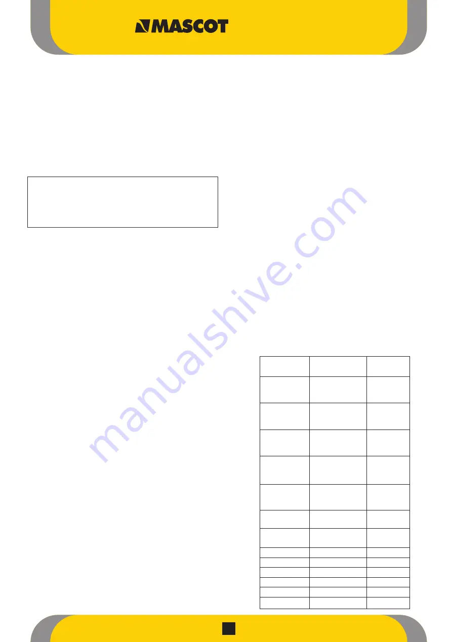
For proper sealing, the torque values as recommended should be
applied to line flange bolting for proper sealing - Refer Table 1
1.
2.
3.
4.
1.
2.
3.
4.
5.
6.
Table 1 : Flange Bolting Torques
Valve
Rating
Torques
Size (In.)
(ft.Lbs.)
150
118
2
300
118
600
118
150
118
3
300
209
600
209
150
118
4
300
209
600
505
150
209
6
300
209
600
505
150
209
8
300
337
600
728
10
150
337
300
728
12
150
337
300
728
14
150
505
16
150
505
18
150
728
20
150
728
24
150
1009
30
150
1009
DiskFlo Control Valves


