


Mas Grup
18
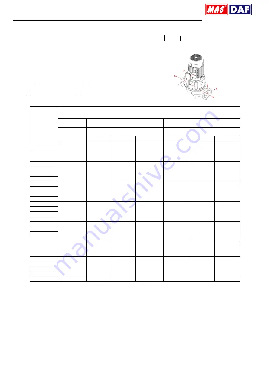
14. FORCES AND MOMENTS AT THE PUMP FLANGES
All of the applied load sif not reached the maximum allowable value, to
provide that the following additional conditions, one of these loads may
exceed the normal limit:
Any component of a force or a moment, must be limited1.4times of
the maximum allowable value,
The actual force sand moments acting on each flange, should provide
the following formula:
2
2
allowable
maximum
actual
2
allowable
maximum
actual
M
M
F
F
In here,
F
and
M
arearithmetic sum of the loads for each
flange at the pump level, without regard of the algebraic signs of the
actual and maximum allowable values.
PUMP
TYPE
FORCES AND MOMENTS
DN FLANGE
SUCTION AND DISCHARGE FLANGE
SUCTION AND DISCHARGE FLANGE
mm
N
Nm
F
y
F
z
F
x
M
y
M
z
M
x
INM-H 40-125
40
595,3
476,2
523,82
428,58
500,01
619,06
INM-H 40-160
INM 40-200
INM 40-250
INM-H 50-125
50
785,7
642,9
714,3
476,2
547,63
666,68
INM-H 50-160
INM 50-200
INM 50-250
INM-H 65-125
65
1000
809,5
880,97
523,82
571,44
714,3
INM-H 65-160
INM 65-200
INM 65-250
INM 80-160
80
1191
976,2
1071,45
547,63
619,06
761,92
INM 80-200
INM 80-250
INM 80-315
INM 100-160
100
1595
1286
1428,6
595,25
690,49
833,35
INM 100-200
INM 100-250
INM 100-315
INM 125-200
125
1881
1524
1690,51
714,3
904,78
1000
INM 125-250
INM 125-315
INM 150-200
150
2381
1929
2142,9
833,35
976,21
1190,5
INM 150-250
INM 150-315
INL 150-360
INL 200-315
200
3040,2
2440,5
2713,8
1065
1223,2
1612,4
Table 6 -
Forces and Moments at The Pump Flanges
Forces at the pump flanges were calculated according toTS EN ISO 5199 standard. The calculations are valid for the materials of cast iron and
bronze. Forces and moments at the flanges that made of stainless material will be approximately twice as moments in the table.