Maruson Technology Corporation
2
ULTIMA SERIES 1K-3KVA | 2012 Jan.
1. Important Safety Warning
Please comply with all warnings and operating instructions in this manual strictly. Save this
manual properly and carefully read the following instructions before installing the unit. Do not
operate this unit before reading through all safety information and operating instructions
carefully.
1-1. Transportation
l
Please transport the UPS system only in the original packaging to protect against
shock and impact.
1-2. Preparation
l
Condensation may occur if the UPS system is moved directly from cold to warm
environment. The UPS system must be absolutely dry before being installed. Please
allow at least two hours for the UPS system to acclimate to the environment.
l
Do not install the UPS system near water or in moist environments.
l
Do not install the UPS system where it would be exposed to direct sunlight or near a
heater.
l
Do not block ventilation holes in the UPS housing.
1-3. Installation
To guarantee UPS normal operation, before connecting devices to the UPS, please
verify that ground and neutral lines of the connected devices are not short circuited.
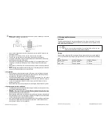
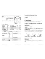
(see Figure 1)
Figure 1
If neutral line and ground line are short circuited, please add isolation transformer
between UPS and devices. (see Figure 2)
Figure 2
Maruson Technology Corporation
17
ULTIMA SERIES 1K-3KVA | 2012 Jan.
6. Specifications
MODEL
ULT-1K(L)
ULT-2K(L)
ULT-3K(L)
CAPACITY*
1000 VA / 800 W
2000 VA / 1600 W
3000 VA / 2400 W
INPUT
Low Line Transfer
160VAC/140VAC/120VAC/110VAC ± 5% or 80VAC/70VAC/60VAC/50 VAC ± 5%
( based on load percentage 100% - 80 % / 80 % - 70 % / 70 - 60 % / 60 % - 0)
Low Line Comeback
168VAC/148VAC/128VAC/118VAC ± 5 % or 84VAC/74VAC/64VAC/54 VAC ± 5 %
( based on load percentage 100% - 80 % / 80 % - 70 % / 70 - 60 % / 60 % - 0)
High Line Transfer
300 VAC ± 5 % or 150 VAC ± 5 %
Voltage
Range
High Line Comeback
290 VAC ± 5 % or 145 VAC ± 5 %
Frequency Range
40 ~ 70 Hz (Auto sensing)
Phase
Single phase with ground
Power Factor
0.98
OUTPUT
Output voltage
208/220/230/240VAC or 110/115/120/127VAC
AC Voltage Regulation
± 1%
Frequency Range
(Synchronized Range)
47 ~ 53 Hz or 57 ~ 63 Hz
Frequency Range (Batt. Mode)
50 Hz ± 0.25 Hz or 60Hz ± 0.3 Hz
Current Crest Ratio
3:1
Harmonic Distortion
3 % THD (Linear Load)
6 % THD (Non-linear Load)
4 % THD (Linear Load)
7 % THD (Non-linear Load)
AC Mode to Batt. Mode
Zero
Transfer
Time
Inverter to Bypass
4 ms (Typical)
Waveform (Batt. Mode)
Pure Sinewave
EFFICIENCY
AC Mode
88.5 % (89% peak)
89.3 % (90% peak)
87%
Battery Mode
83.7 % (86% peak)
88.2 % (89% peak)
85%
BATTERY
Battery Type
12V / 9Ah
Battery Numbers
2
4
6
Charging Current
(max.)
1.0 A
Standard
Model
Charging Voltage
27.4 VDC ± 1%
54.7 VDC ± 1%
82.1 VDC ± 1%
Battery Type &
Numbers
Depending on the capacity of external batteries
Charging Current
1A / 2A / 5 A (Default)
1A / 2A / 4A / 8A (Default)
Long
Runtime
Model
Charging Voltage
27.4 VDC ± 1%
54.7 VDC ± 1%
82.1 VDC ± 1%
PHYSICAL
Dimensions
(DxWxH)(mm)
400 X 146 X 205
397 x 145 x 220
421 x 190 x 318
Standard
Model
Net Weight (kgs)
9.3
17.8
28.8
Dimensions
(DxWxH)(mm)
400 X 146 X 205
397 x 145 x 220
421 x 190 x 318
Long
Runtime
Model
Net Weight (kgs)
4.8
7.4
13.5
ENVIRONMENT
Operation Humidity
20-90 % RH @ 0- 40°C (non-condensing)
Noise Level
Less than 45dBA @ 1 Meter
MANAGEMENT
Smart RS-232 Port/Card
Supports Windows® 2000/2003/XP/Vista/2008, Windows® 7, Linux, Unix, and
MAC
Intelligent Slot
Power management from SNMP manager and web browser
* Derate capacity to 80% when the output voltage is adjusted to 208VAC.


