2
2. PRODUCT SPECIFIC SAFETY INFORMATION
Measurement Category IV (CAT IV)
is applicable to test and
measuring equipment connected at the source of the building’s low-
voltage MAINS installation.
The specifi ed measurement category means the phase sequence
indicator will be safe to the user if inadvertently connected to a voltage
up to 600V AC/DC to earth within a CAT IV environment. It
does
not
mean it can be used to test for a voltage beyond its maximum
specifi ed limits.
2.1 Precautions
This product has been designed with your safety in mind, but please
pay attention to the following warnings and cautions before use.
Warning
The phase sequence indicator must only be used by a skilled and
competent person who is familiar with the relevant regulations,
the safety risks involved and the consequent normal safe working
practices.
Before use check the unit for cracks or any other damage. The cables
have black outer and contrasting inner insulation, to allow damage to
the cables to be easily identifi ed. If there is any doubt the unit should
not be used
.
Always verify the unit is functioning correctly on a known correctly
sequenced 3-phase voltage source before and after use.
Do not use
the unit if the unit does not give the correct indications.
Always keep your fi ngers behind the test probe fi nger guards. Never
touch the exposed metal probe tips.
PC15250 instructions rev3.indd 4
09/07/2013 08:25:32
3
The socket tester is not intended to determine if circuits being
tested are dead. The correct testing methods should be used to do
this.
If the LED indicators do not illuminate, this does not necessarily
mean all three phases under test are dead. Two phases could be
open circuit, but one phase could still be live.
Caution
Avoid severe mechanical shock or vibration and extreme
temperature.
PC15250 instructions rev3.indd 5
09/07/2013 08:25:32
4
OPERATION
3.1
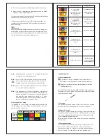
Description of LED Indicators
L1
L2
L3
THREE LIT: CORRECT
ONE LIT: THAT PHASE FAULTY
PHASE
PHASE SEQUENCE
L1
L2
L3
L1
L2
L3
*
Both phase sequence LED’s are illuminated if a phase is missing.
3.2 Use of Test Probe Shrouds
The shrouds around the L1 and L2 test probes are normally sprung
forwards to IP 2X rating and are retractable.
For optimum safety, the shrouds should be allowed to spring forward
freely whenever the probe tips are removed from a location under test.
If desired, and before the unit is connected to any source of voltage, the
shrouds can be locked back by pushing and twisting 90°.
The probe tips will be exposed by 3 ± 0.5mm. In this position they are
GS38 compliant.
3.3 Proving Check
Before and after use, verify the unit is functioning correctly on a known
correctly sequenced 3-phase voltage source of 50V to 600V phase to
phase, and frequency of 40Hz to 60Hz.
All phases present when all
three LED’s illuminated
One LED illuminated
indicates the respective
phase is missing
Incorrect phase
sequence of
L1, L3, L2 when
illuminated*
Correct phase
sequence of
L1, L2, L3 when
illuminated*
PC15250 instructions rev3.indd 8
09/07/2013 08:25:33
5
Connect the L1, L2 and L3 test probes respectively to the L1, L2 and
L3 phases of the voltage source.
The PC15250 must indicate as shown below.
L1, L2 & L3 LED’s must illuminate red
Phase Sequence L1 L2 L3 LED must
illuminate red
Phase Sequence LED L1 L3 L2 LED
must be extinguished
L1
L2
L3
THREE LIT: CORRECT
ONE LIT: THAT PHASE FAULTY
PHASE
PHASE SEQUENCE
L1
L2
L3
L1
L2
L3
Do not use
the unit if the unit does not give the correct indications
above.
During this verifi cation emphasis should also be placed upon the
fl exing of the individual cables along their length, and particularly at
the entry points to the hand held elements, to confi rm that the cable/s
have not fractured.
3.4 Testing a 3 Phase Distribution System
Take all required safety precautions when connecting the test probes
to the 3-phase electrical distribution system to be tested.
1. The three test probes are marked L1, L2, L3. These relate to the
L1, L2, L3 LED’s on the instrument facia.
2. To determine phase presence and phase sequence, connect
the test probes to the phase cables of the 3-phase electrical
distribution system to be tested. Refer to table 2 of section 3.5 to
determine to which cables to connect L1, L2 and L3 (see Note 2).
PC15250 instructions rev3.indd 9
09/07/2013 08:25:33


