background image

User guide

 23

To set up a 

Control

 function:

1. Use the 

Add Control

 button to create a new 

Control

.

2. Select the DMX channel you want to use to control parameters in the display. This channel will give you 

8-bit control.

3. If you want to use 16-bit fine control, check the 

16-bit Control

 checkbox and specify which 

High DMX 

Channel

 you want to use for fine control.

4. Enter minimum and maximum values under 

Range

 if you want to define the range of DMX values that will 

be used to control the variable. Values from 0 to 255 can be defined for 8-bit control and from 0 to 65535 
for 16-bit control.

Setting up Variables

The 

Variables

 you can control via DMX using a 

Control

 in the P3-100 interface appear on the right of the 

Remote Control

 window. You can create new 

Variables

 using the 

Add Variable

 button to the right of the 

Add Control

 button, and you can edit the names of your 

Variables

. You can delete a 

Variable

 by clicking on 

its 

 button, and you can expand and collapse the setup details of each 

Variable

 using its 

 button.

Pre-programmed Variables

The first two 

Variables

 are pre-programmed and cannot be deleted. They should both be set up as non-fade 

(snap) controls on the DMX controller.

• The first 

Variable

 allows you to 

Freeze

 the video image, 

Blackout

 the entire installation and display 

Test 

patterns

 on the entire installation. Selecting 

Live Input

 lets you return from any of these three modes to 

normal video playback.

• The second 

Variable

Capture Properties

, calls up any configuration presets saved under 

Presets

 at the 

bottom of the 

Video Setup

 window.

To assign a 

Control

 to one of the two pre-programmed 

Variables

, select it from the drop-down list for that 

Variable

. The DMX channel (or channels in 16-bit mode) and other settings are now linked to that variable.

Custom Variables

You can create two types of custom variable:

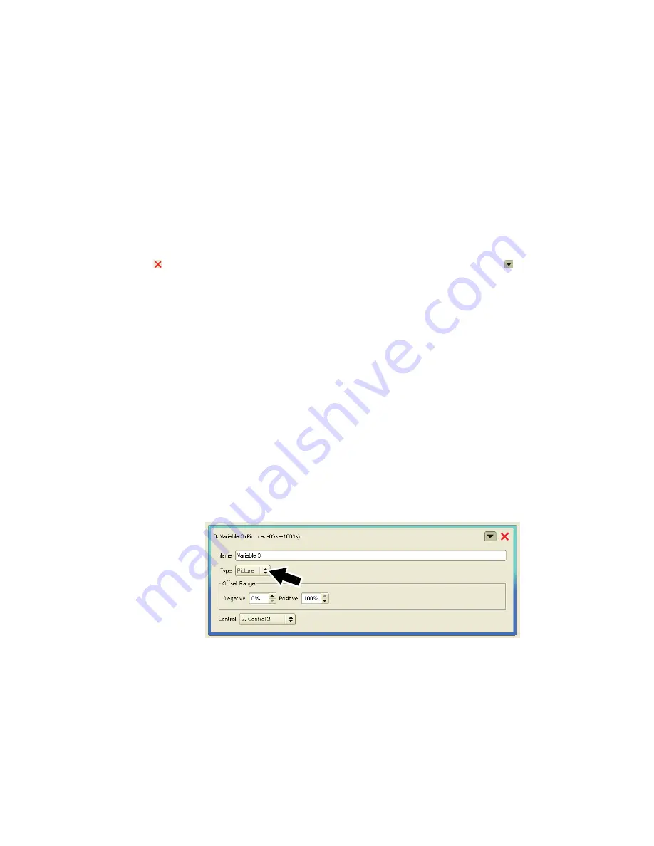
Picture


Variables

 (see arrow in Figure 23) let you use DMX commands to control the overall intensity and/or 

individual color intensities of one or more panels. 

Position


Variables

 let you use DMX commands to control the x-y coordinates of panels in the video frame. In 

other words they let you move the portion of the video image you display on panels from a DMX controller.

Setting up a Picture Variable

1. Use the 

Add Variable

 button at the top of the 

Remote Control

 window to create a new variable. If it is the 

first custom variable you create it will have the name 

Variable 3

 by default, but you can rename it in the 

Name

 box.

Figure 23: 

Picture

 variable

Содержание P3-100

Страница 1: ...P3 100 System Controller Installation and Safety Manual User Guide TM ...

Страница 2: ...oss consequential or economic loss or any other loss occasioned by the use of inability to use or reliance on the information contained in this manual The Martin logo the Martin name and all other trademarks in this document pertaining to services or products by Martin Professional A S or its affiliates and subsidiaries are trademarks owned or licensed by Martin Professional A S or its affiliates ...

Страница 3: ...o replace the power plug to match any other type of power outlet socket install a grounding type earthed listed power plug rated 5 A minimum as directed in this manual In all cases check that the power plug connects correctly to ground earth Isolate the product from AC mains power if the power cable or power plug is in any way damaged defective or showing signs of overheating Do not reapply power ...

Страница 4: ...e only Never attempt to bypass a fuse Replace the internal CR2032 lithium button cell battery with one of the same type only Risk of explosion if battery replaced by incorrect type Dispose of used batteries according to the manufacturer s instructions A T T E N T I O N En cas d équipement enfichable la prise doit être montée près de l équipement et doit offrir un accès facile Il y a un danger d ex...

Страница 5: ...ting up the P3 100 and panels 12 Setting up video input 19 Saving presets 21 Remote control via DMX 22 Viewing live system information and the system log 25 Managing panel utilities from the P3 100 25 Shutting down the system 26 Service 27 Updating and reloading P3 100 firmware 27 Installing new LC Plus panel firmware from the P3 100 27 System and hardware status information 29 Fuse replacement 30...

Страница 6: ...rtemp lights if the P3 100 has exceeded its maximum safe operating temperature A thermal protection circuit throttles down the processor if this happens Reset lets you carry out a forced reset if the P3 100 application freezes and you cannot reboot the processor normally for example Use the tip of a ballpoint pen to push the reset button The P3 100 constantly stores data in its onboard flash memor...

Страница 7: ... the Y and C Pb connectors for S Video Use the Y C Pb and Pr connectors for component video Typical connector color coding is Green to Y Blue to Pb and Red to Pr F DMX input 5 pin locking XLR For connection from a DMX controller G Ethernet port 2 P3 output RJ 45 P3 signal output Connect to the video panel installation via an Ethernet cable H Ethernet port 1 RJ 45 Communication with P3 100 s intern...

Страница 8: ...output resolution Genlock Image rotation Scaling De interlacing Gamma curve adjustment Comments or suggestions regarding this user manual may be e mailed to service martin dk or posted to Technical Documentation Martin Professional A S Olof Palmes Allé 18 DK 8200 Aarhus N Denmark Installation The P3 100 System Controller is designed to be rack mounted in a central control room for fixed installati...

Страница 9: ...ces in potential at different points in the installation There is no power on off switch on the P3 100 Apply and shut down power using an external switch at the power outlet or at the main switchboard Avoid applying power by inserting or removing live power connectors as this will cause arcing at the connector contacts that may damage devices and connectors Installing power plugs to match local po...

Страница 10: ...ion including important safety information refer to the LC Plus user documentation supplied with panels and available for download free of charge from www martin com Figure 3 System layout DVI Analog video Analog video Monitor Mouse Keyboard P3 100 Controller P3 signal 1GB Ethernet switch required 1GB Ethernet switch required 100 m Max 50 panels per daisy chain if installation exceeds 50 panels if...

Страница 11: ...t be recognized the P3 100 defaults to 1024x768 Making connections and applying power 1 Check that the LC Plus panel installation has been safely connected See Figure 3 for a system layout diagram 2 See Figure 2 on page 7 On the P3 100 s rear panel Connect the Ethernet data cable from the LC Plus panels to Ethernet port 2 G Note that Ethernet port 1 H is available for future data connection option...

Страница 12: ... look for a configuration file either in the P3 100 s internal flash memory or on a removable USB memory storage device Select Create New to create a new configuration file and save it in the P3 100 s internal flash memory 2 If you want a portable backup of a configuration file you have saved in the P3 100 s internal flash memory you can copy the file to a USB memory device at any time using the S...

Страница 13: ...e setup procedure If panels have been detected there is nothing to stop you positioning them in the video frame and configuring them immediately but if you are not familiar with the P3 100 we recommend you follow the two stage procedure below in which you first set up an on screen virtual installation and then map detected panels to that installation Working offline You can set up complete configu...

Страница 14: ...f the P3 100 has auto detected panels that are connected to it and these panels have the same display address as the panels you add to the on screen installation they will automatically be assigned to the panels in your on screen installation and appear in the Configured Devices list with a green bullet point Ignore this for the moment you will assign physical panels to the on screen installation ...

Страница 15: ...in Figure 10 because it has been selected by clicking on it 8 See Figure 11 If necessary use the Magnification tools to adjust the magnification of the video frame on the right of your monitor screen until you have a comfortable size to work with Figure 10 An on screen virtual installation with 4 panels Figure 11 Magnification tools ...

Страница 16: ...n screen installation The P3 100 auto detects LC Plus panels that are powered on and connected to it Panels keep their display addresses in memory when powered off so depending on how a detected panel was set up the last time it was installed its display address may be wrong or more than one panel may have the same display address Your first task is therefore to set the detected panels display add...

Страница 17: ...splay address for its position in the installation you must either a enter Device Properties for that panel and set its display address to the correct number as described above or b manually set the correct display address for that panel using the control buttons on the back of the panel base 3 Once you have given correct display addresses to panels in the Configured Devices window repeat this pro...

Страница 18: ...he button The LC Plus panels in the installation will now show their display addresses as large numbers An arrow will indicate their up down orientation and angles will indicate panel corners 5 Check that display addresses are correct If you have made a mistake during addressing go back and adjust any incorrect display addresses as described earlier until the installation is correctly laid out 6 D...

Страница 19: ...ore connecting or before powering up the media server or video source 1 Open the Video Input window 2 See Figure 17 The Resolution box indicates the current video input resolution This must match the resolution of the incoming video signal Adjust if necessary 3 Click on the EDID button to open the Configure EDID pop up window The checkboxes for resolution and refresh rate here determine the EDID i...

Страница 20: ...ou scale down the video frame the more of the frame you can display on an array of LC panels and the greater the degree of pixellation as the P3 100 resamples the video image You can scale down to a maximum reduction factor of 8 8 If necessary use the Magnification tools see Figure 11 on page 15 to adjust the magnification of the video frame on the right of your monitor screen until you have a com...

Страница 21: ...Figure 20 where you can fine tune the gamma curve of your display 3 If you click on New and enter a name for any gamma curve you edit it will be saved as a preset gamma curve when you click on the Close button 4 With the Link RGB checkbox arrowed checked you can adjust the gamma curve for all three colors together If you uncheck the Link RGB checkbox you can adjust the gamma curve separately for e...

Страница 22: ...play on LC PLus panels using Controls and Variables Controls are functions that contain DMX channel and setup options Variables are functions that contain panel display options Any Control can be set to control any Variable or to control multiple Variables Setting up Controls To set up a Control open the Remote Control window see Figure 22 Controls appear on the left of the window You can create n...

Страница 23: ...s non fade snap controls on the DMX controller The first Variable allows you to Freeze the video image Blackout the entire installation and display Test patterns on the entire installation Selecting Live Input lets you return from any of these three modes to normal video playback The second Variable Capture Properties calls up any configuration presets saved under Presets at the bottom of the Vide...

Страница 24: ... control any combination of overall intensity and individual RGB color intensities In Figure 24 only the panel with display number 1 in the installation an LC 2140 Model has been selected so the Variable will only be applied to this panel Variable 3 has been selected for Intensity and No Variable selected for RGB intensities so Variable 3 will control the overall intensity of panel 1 Setting up a ...

Страница 25: ... 1 4 diagonally relative to the video image Note that if panels are moved up relative to the video image the image will appear to move down when you view the installation Viewing live system information and the system log 1 See Figure 26 Open the Live window and select Info under Log Level arrowed The P3 100 keeps a running log of system events that can be very useful during troubleshooting Managi...

Страница 26: ...nt to store on the USB memory device 2 Click on the Shutdown button at the top right of the screen see Figure 4 on page 11 When the P3 100 displays a message telling you that it is safe to shut down the system cut power to the P3 100 Function Shortcut View hardware settings dialog box Ctrl S Zoom in out Ctrl Ctrl mouse wheel Vertical scroll mouse wheel Horizontal scroll Alt mouse wheel Select all ...

Страница 27: ... To reload the P3 100 System Controller firmware 1 Connect a USB memory device loaded with the P3 100 System Controller firmware to any of the P3 100 s USB ports 2 See Figure 27 Click on the Hardware Settings button arrowed 3 See Figure 28 The current firmware version is displayed in the Firmware panel arrowed Click on the Reload Firmware button and browse to the p3 100sc XXX fw file on the USB me...

Страница 28: ...at panel at the bottom of the screen 3 Click on the Reload Firmware button at the bottom of the Device Properties and follow the instructions on the monitor screen 4 Finally de select the panel in the Configured Devices list Updating firmware in multiple panels See Figure 29 If you connect to panels that are running outdated firmware the P3 100 may show a warning and ask whether it should automati...

Страница 29: ...ormation via a network To access status info over a network 1 Plug a network cable into Ethernet port 1 on the P3 100 s rear panel to connect the P3 100 to the network 2 See Figure 27 on page 27 Click on the Hardware Settings button arrowed 3 See Figure 28 on page 27 If using DHCP make sure the Use DHCP checkbox under Network Settings is checked Otherwise enter static IP address subnet mask and ga...

Страница 30: ...ll If you suspect that the internal batteries are no longer serviceable contact Martin Professional for replacement Error codes In the event of a system error the LEDs on the front panel indicate error codes by a repeating pattern of flashing the LEDs a number of times in succession followed by a 1 second pause Main board errors are indicated by the bottom four LEDs only flashing as follows 2 flas...

Страница 31: ...ician Other device e g Ethernet switch on P3 link defective Replace with a device known to be operating correctly Have faulty device tested and serviced All LCP panels and or monitor screen display video incorrectly or do not display video at all Unusable video signal or defective video source Check video source Fault on P3 link Inspect connections and cables Correct poor connections Repair or rep...

Страница 32: ...l type Gigabit Ethernet Protocol Proprietary Martin P3 Hot pluggable Yes electrically isolated at all connections Cable type CAT 5e Cable length Up to 100 m 328 ft between any 2 devices extendable with Ethernet switch Max number of panels per chain 50 extendable with Ethernet switch Latency between first and last panel None C o ns t ru c tio n Housing Steel aluminum Color Matt black Protection rat...

Страница 33: ...ntation is also available for download free of charge from the Product Support area at www martin com R el at e d P r od u ct s Martin Maxedia PRO System Media Server EU P N 90732520 Martin Maxedia PRO System Media Server US P N 90732530 Martin Maxedia Compact System Media Server EU US P N 90732540 O r d e r i ng I nf o r m a t i o n Martin P3 100 System Controller P N 90721010 LC Plus 2140 packed...

Страница 34: ...34 P3 100 user manual Notes ...

Страница 35: ......

Страница 36: ...www martin com Olof Palmes Allé 18 8200 Aarhus N Denmark Tel 45 8740 0000 Fax 45 8740 0010 ...

Отзывы: