background image

  27 


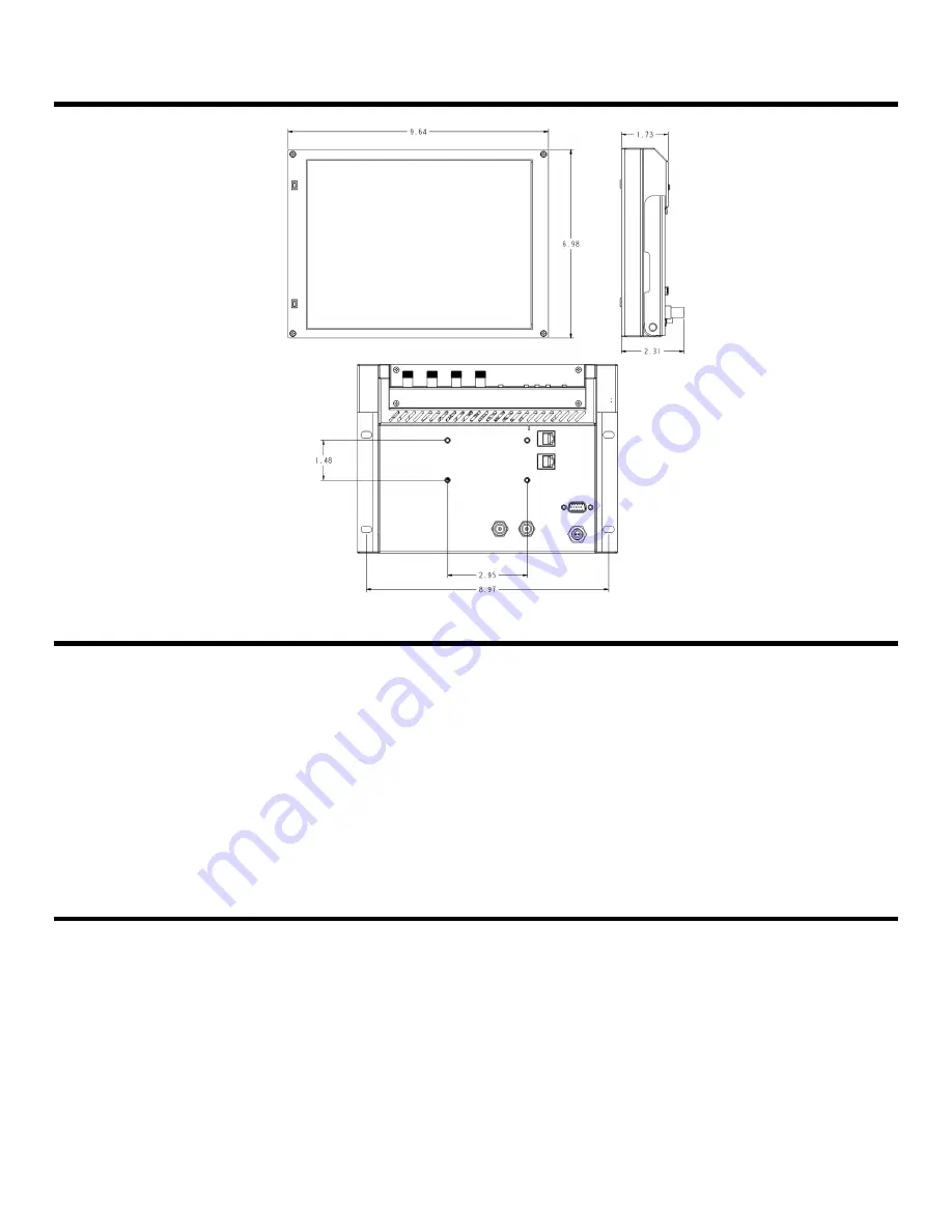
Specifications (continued)


Maintenance 


  Screen Cleaning 

Periodically clean the screen surface using ammonia-free cleaning wipes (Marshall Part No. 

V-HWP-K). A clean micro-

fiber cloth can also be used using only non-abrasive and ammonia-free cleaning agents. Do not use paper towels. 
Paper towel fibers are coarse and may scratch the surface of the polycarbonate faceplate or leave streaks on the 
surface.  Antistatic and fingerprint resistant cleaning agents are recommended. Do not apply excessive pressure to the 
screen to avoid damaging the LCD. 


  Faceplate Dusting 

Dust the unit with a soft, damp cloth or chamois. Dry or abrasive cloths may cause electrostatic charge on the surface, 
attracting dust particles. Neutralize static electricity effects by using the recommended cleaning and polishing practice. 


Warranty

 
Marshall Electronics warranties to the first consumer that this 

V-R1041-IMD-TE4U LCD monitor will, under normal use, be 

free from defects in workmanship and materials, when received in its original container, for a period of one year from the 
purchase date. This warranty is extended to the first consumer only, and proof of purchase is necessary to honor the 
warranty. If there is no proof of purchase provided with a warranty claim, Marshall Electronics reserves the right not to 
honor the warranty set forth above. Therefore, labor and parts may be charged to the consumer. This warranty does not 
apply to the product exterior or cosmetics. Misuse, abnormal handling, alterations or modifications in design or 
construction void this warranty. 

It is considered normal for a minimal amount of pixels, not to exceed three, to fail on the 

periphery of the display active viewing area. Marshall Electronics reserves the option to refuse service for display pixel 
failure if deemed unobtrusive to effective use of the monitor by our technicians. No sales personnel of the seller or any 
other person is authorized to make any warranties other than those described above, or to extend the duration of any 
warranties on behalf of Marshall Electronics, beyond the time period described above. Due to constant effort to improve 
products and product features, specifications may change without notice.


Содержание V-R1041-IMD-TE4U

Страница 1: ...Marshall Electronics V R1041 IMD TE4U High Definition LCD Monitor with In Monitor Display Operating Instructions...

Страница 2: ...lue Only Mode 11 Pixel to Pixel Mode 12 Aspect Ratio Settings 12 Curtain Color 13 COLOR CONFIGURATION SUBMENU 14 Ctemp Gamma 14 Red Green Blue Offset 14 Red Green Blue Offset 14 Gray Levels 15 User De...

Страница 3: ...wide viewing angles color temperature adjustment adjustment settings memory frame markers Pixel to Pixel mode Blue Only mode and user definable function buttons The V R1041 IMD TE4U can also be used...

Страница 4: ...MD TE4U is shipped with a 20 mounting bracket on the bottom side allowing the monitor to be flexibly mounted to a camera or tripod A 35 x 75mm hole pattern is also included on the back panel so the mo...

Страница 5: ...n menu See User Definable Function Buttons Page 15 RotoMenu Knob The RotoMenu knob is alternate means of accessing and navigating the main menu using only a single control Image Adjustment Knobs Use t...

Страница 6: ...ace HD 15 Both LED tally and OSD tally can be activated via the HD 15 connector by connecting the corresponding pin to ground A variety of external devices can be used to perform the contact closure N...

Страница 7: ...onochrome Save Defaults Back Save Mfg Load Config Mfg User 1 User 2 User 3 User 4 User 5 User 6 Save Config User 1 User 2 User 3 User 4 User 5 User 6 Main Board Main board firmware version number disp...

Страница 8: ...menu or each submenu Press the SELECT button to enter a submenu or choose a setting Press the MENU button to exit the main menu or return to the main menu from a submenu Using the RotoMenu knob Press...

Страница 9: ...n the screen when in 16 9 mode This setting is disabled when the aspect ratio is set to 4 3 or when Pixel to Pixel mode is enabled Off No Marker 95 Safe Area 93 Safe Area 90 Safe Area 88 Safe Area 80...

Страница 10: ...88 Safe Area 80 Safe Area 4 3 Marker Examples Marker Background Use this setting to choose how selected markers are displayed on the screen Off The marker is superimposed on the complete image 50 Gra...

Страница 11: ...he monitor to SMPTE color bars with the following procedure 1 Allow the monitor to warm up for at least 5 10 minutes 2 Display SMPTE split field color bars on the monitor using an external source 3 En...

Страница 12: ...onitor has a native resolution of 1024 x 768 RGB pixels incoming images are automatically scaled to fit the screen In 4 3 mode images are scaled up or down to fill the entire 4 3 screen 1024 x 768 IMD...

Страница 13: ...tinued Aspect Ratio Settings continued Curtain Color Use this setting to choose the default color displayed on the screen when no video input is present Available colors are blue red green white and b...

Страница 14: ...just the color temperature of the display Each setting adjusts the offset or brightness of each individual color component These settings will affect whichever color temperature preset is selected Red...

Страница 15: ...panel of the monitor The following options are available for each button Marker Enable and rotate amongst marker settings choices depend on aspect ratio setting Center Marker Enable disable center mar...

Страница 16: ...e loaded by selecting MFG Factory defaults cannot be overwritten Use the SAVE CONFIG menu to save the current settings to a preset from USR1 USR6 Save Defaults Use this setting to save the current val...

Страница 17: ...aptive de interlacing algorithm Film cadence detection is disabled Motion adaptive interlacing uses a variety of real time algorithms to perform the best possible deinterlacing based on the content In...

Страница 18: ...nt is ignored Film Indicator Use the Film Indicator setting to enable or disable the film mode detection icon If the Film Indicator is set to On a green square will appear in the top left corner of th...

Страница 19: ...MD text commands see IMD Configuration Submenu for details page 22 Status Display Use this setting to enable or disable status display When enabled the current video input standard is displayed on the...

Страница 20: ...aneously by subdividing each tally indicator RG Red tally is shown at the bottom left of the screen and green is shown at the bottom right GR Green tally is shown at the bottom left of the screen and...

Страница 21: ...reen Time code is de embedded from the vertical ancillary data VANC within the SDI signal Two types of time code can be selected to display on the screen LTC linear time code or VITC vertical interval...

Страница 22: ...rshall Electronics for the latest protocol compatibility Image Video Use the Image Video protocol setting when controlling the IMD from an Image Video tally controller or other controlling device whic...

Страница 23: ...nged and use the and buttons to scroll through character options Press ENTER to choose a character IMD Baud Rate Use this setting to choose the baud rate The baud rate must be set in conjunction with...

Страница 24: ...s via the Image Video serial protocol LED and OSD tally will be disabled in this mode as Image Video tally states are manifested in the text color and other parameters This mode requires the IMD Tally...

Страница 25: ...number of characters received by the UART Tx Total number of characters transmitted by the UART Serial Errors P Number of parity errors F Number of framing errors O Number of FIFO overrun errors Packe...

Страница 26: ...15 Activation requires contact closure of pin to ground on the HD 15 connector Pin No Signal 1 Monitor 1 Green 2 Monitor 1 Red 3 Monitor 1 Yellow OSD tally only 4 Ground 5 Ground 6 N C 7 N C 8 N C 9 N...

Страница 27: ...its original container for a period of one year from the purchase date This warranty is extended to the first consumer only and proof of purchase is necessary to honor the warranty If there is no proo...

Страница 28: ...28 Marshall Electronics Inc 1910 East Maple Ave El Segundo CA 90245 Tel 800 800 6608 310 333 0606 Fax 310 333 0688 www LCDRacks com sales lcdracks com V2 0...

Отзывы: