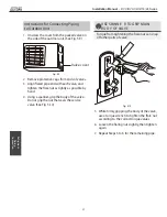
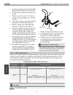
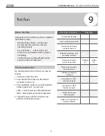
background image

Installation Manual  -  

DVC/DVH 09/12/18/24 Series

Page 23 

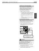
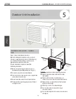
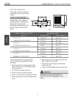
If you will install the unit on a wall-mounted 
bracket 

, do the following:

 CAUTION

Before installing a wall-mounted unit, make 
sure that the wall is made of solid brick, 
concrete, or of similarly strong material. 

The


wall must be able to support at least four 
times the weight of the unit.

1.

Mark the position of bracket holes based on
dimensions in the Unit Mounting Dimensions
chart.

2.

Pre-drill the holes for the expansion bolts.

3.

Clean dust and debris away from holes.

4.

Place a washer and nut on the end of each
expansion bolt.

5.

Thread expansion bolts through holes in
mounting brackets, put mounting brackets
in position, and hammer expansion bolts into

the wall.

6.

Check that the mounting brackets are level.

7.

Carefully lift unit and place its mounting feet
on brackets.

8.

Bolt the unit firmly to the brackets.

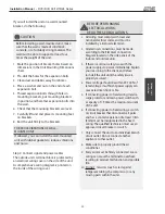
TO REDUCE VIBRATIONS OF WALL-
MOUNTED UNIT

If allowed, you can install the wall-mounted 
unit with rubber gaskets to reduce vibrations 
and noise.

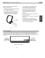
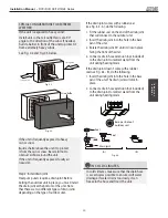
Step 4: Connect signal and power cables

The outside unit’s terminal block is protected by 
an electrical wiring cover on the side of the unit. 
A comprehensive wiring diagram is printed on 
the inside of the wiring cover.

BEFORE PERFORMING 
ELECTRICAL WORK, 


READ THESE REGULATIONS

1.

All wiring must comply with local and
national electrical codes, and must be
installed by a licensed electrician.

2.

All electrical connections must be made
according to the Electrical Connection
Diagram located on the side panels of the
indoor and outdoor units.

3.

If there is a serious safety issue with the
power supply, stop work immediately. Explain
your reasoning to the client, and refuse
to install the unit until the safety issue is
properly resolved.

4.

Power voltage should be within 90-100% of
rated voltage. Insufficient power supply can
cause electrical shock or fire.

5.

If connecting power to fixed wiring, install a
surge protector and main power switch with
a capacity of 1.5 times the maximum current
of the unit.

6.

If connecting power to fixed wiring, a switch
or circuit breaker that disconnects all poles
and has a contact separation of at least 1/8in
(3mm) must be incorporated in the fixed
wiring. The qualified technician must use an
approved circuit breaker or switch.

7.

Only connect the unit to an individual branch
circuit outlet. Do not connect another
appliance to that outlet.

8.

Make sure to properly ground the air
conditioner.

9.

Every wire must be firmly connected. Loose
wiring can cause the terminal to overheat,
resulting in product malfunction and possible
fire.

10.

Do not

  let wires touch or rest against

refrigerant tubing, the compressor, or any
moving parts within the unit.

Outdoor Unit 

Installation

22

Содержание A-DVH09SF-0

Страница 1: ...sdelivers com Installation Manual DVC DVH Series Inverter Single Zone Ductless Mini Split A DVC DVH 09SF A DVC DVH 12SF A DVC DVH 18SF A DVC DVH 24SF B DVC DVH 09SF B DVC DVH 12SF B DVC DVH 18SF B DVC DVH 24SF ...

Страница 2: ...iping 12 4 Prepare refrigerant piping 14 5 Connect drain hose 15 6 Connect signal cable 17 7 Wrap piping and cables 18 8 Connect indoor power wire 18 9 Mount indoor unit 18 Outdoor Unit Installation 20 8 1 Select installation location 20 2 Install drain joint 21 3 Anchor outdoor unit 22 4 Connect signal and power cables 23 Safety Precautions 4 0 1 5 Accessories 6 2 4 Unit Parts 10 3 Installation S...

Страница 3: ...ngth 25 B Connection Instructions Refrigerant Piping 25 1 Cut pipe 25 2 Remove burrs 26 3 Flare pipe ends 26 4 Connect pipes 27 Air Evacuation 29 1 Evacuation Instructions 29 2 Note on Adding Refrigerant 30 Electrical and Gas Leak Checks 31 Test Run 32 European Disposal Guidelines 34 6 7 8 9 10 MC MC ...

Страница 4: ...se abnormally high pressure in the refrigeration cycle This can cause explosion and injury allow children to play with the air conditioner Children must be supervised around the unit at all times 1 Installation must be performed by an authorized dealer or specialist Defective installation can cause water leakage electrical shock or fire 2 Installation must be performed according to the installatio...

Страница 5: ... units that have an auxiliary electric heater do not install the unit within 1 meter 3 feet of any combustible materials Do not install the unit in a location that may be exposed to combustible gas leaks If combustible gas accumulates around the unit it may cause fire Do not operate your air conditioner in a wet room such as a bathroom or laundry room Too much exposure to water can cause electrica...

Страница 6: ...ntroller holder ST2 9 x 10 Remote controller holder Dry battery AAA LR03 Seal Drain joint Mounting plate 1 Accessories The air conditioning system comes with the following accessories Use all of the installation parts and accessories to install the air conditioner Improper installation may result in water leakage electrical shock and fire or cause the equipment to fail 5 5 2 1 Optional Parts 2 Pag...

Страница 7: ...421 548 754 IMPORTANT NOTE Read this manual carefully before installing or operating your new air conditioning unit Make sure to save this manual for future reference Installation Manual Aurora Series All Model Numbers Name Shape Quantity Parts you must purchase Consult thedealer about the pipe size Connecting pipe assembly Liquid side Gas side Φ6 35 1 4i n Φ9 52 3 8in Φ9 52 3 8in Φ12 7 1 2in Φ16 ...

Страница 8: ...7 Page 8 Installation Summary Indoor Unit 2 Installation Overview Select Installation Location Page 11 Attach Mounting Plate Page 12 Drill Wall Hole Page 12 Determine Wall Hole Position Page 12 1 2 3 4 12cm 4 75in 2 3m 90 55in 12cm 4 75in 15cm 5 9in ...

Страница 9: ... 9 Mount Indoor Unit Page 18 STEP 8 Wrap Piping and Cable Page 18 1 2 3 Connect Piping Page 25 Connect Wiring Page 17 Prepare Drain Hose Page 14 5 6 7 8 9 Installation Overview NOTE ON INDOOR OUTDOOR COMMMUNICATION CIRCUIT USE ONLY AWG 14 4 STRANDED WIRE ...

Страница 10: ... for explanatory purposes The actual shape of your indoor unit may be slightly different The actual shape shall prevail Wall Mounting Plate Power Cable Some Units Refrigerant Piping Signal Cable Remote Control Some Units Drainage Pipe Louver Remote Holder Functional Filter On Front of Main Filter Some Units Front Panel Outdoor Unit Power Cable Some Units ...

Страница 11: ... the location will not vibrate Strong enough to support the weight of the unit A location at least 3 1 2 ft from all other electrical devices e g TV radio computer DO NOT install unit in the following locations Near any source of heat steam or combustible gas Near flammable items such as curtains or clothing Near any obstacle that might block air circulation Near the doorway In a location subject ...

Страница 12: ...ure the mounting plate to the wall by tightening the screws directly into the clip anchors Step 3 Drill wall hole for connective piping You must drill a hole in the wall for refrigerant piping the drainage pipe and the signal cable that will connect the indoor and outdoor units 1 Determine the location of the wall hole based on the position of the mounting plate Refer to Mounting Plate Dimensions ...

Страница 13: ...r unit outline 722mm 28 45in 49mm 1 95in 192mm 7 55in 232mm 9 15in 426mm 16 8in 128mm 5 05in 43mm 1 7in 297mm 11 7in Left rear wall hole 65mm 2 5in Right rear wall hole 65mm 2 5in Indoor unit outline 802mm 31 6in 43mm 1 7in 43mm 1 7in 144mm 5 65in 58mm 2 3in 319mm 12 55in 57mm 2 25in 40mm 1 55in Right rear wall hole 65mm 2 5in Model C 965mm 38in 138mm 5 45in 34mm 1 35in Indoor unit outline 219mm 8...

Страница 14: ...rs if the plastic panel is too difficult to remove by hand 3 Use scissors to cut down the length of the insulating sleeve to reveal about 15cm 6in of the refrigerant piping This serves two purposes To facilitate the Refrigerant Piping Connection process To facilitate Gas Leak Checks and enable you to check for dents 4 If existing connective piping is already embedded in the wall proceed directly t...

Страница 15: ...ove the air filter and pour a small amount of water into the drain pan to make sure that water flows from the unit smoothly NOTE ON DRAIN HOSE PLACEMENT Make sure to arrange the drain hose according to Fig 3 5 DO NOT kink the drain hose DO NOT create a water trap DO NOT put the end of drain hose in water or a container that will collect water PLUG THE UNUSED DRAIN HOLE To prevent unwanted leaks yo...

Страница 16: ...tch with a capacity of 1 5 times the maximum current of the unit 6 If connecting power to fixed wiring a switch or circuit breaker that disconnects all poles and has a contact separation of at least 1 8in 3mm must be incorporated in the fixed wiring The qualified technician must use an approved circuit breaker or switch 7 Only connect the unit to an individual branch circuit outlet Do not connect ...

Страница 17: ...ercurrent protection The specifications of the fuse are printed on the circuit board such as T3 15A 250VAC T5A 250VAC etc 1 Prepare the cable for connection a Using wire strippers strip the rubber jacket from both ends of signal cable to reveal about 40mm 1 57in of the wires inside b Strip the insulation from the ends of the wires c Using wire crimper crimp u type lugs on the ends of the wires PAY...

Страница 18: ...able with any other wiring 2 Using adhesive vinyl tape attach the drain hose to the underside of the refrigerant pipes 3 Using insulation tape wrap the signal wire refrigerant pipes and drain hose tightly together Double check that all items are bundled in accordance with Fig 3 10 DO NOT WRAP ENDS OF PIPING When wrapping the bundle keep the ends of the piping unwrapped You need to access them to t...

Страница 19: ...of this manual for instructions 4 Keep pipe connection point exposed to perform the leak test refer to Electrical Checks and Leak Checks section of this manual 5 After the leak test wrap the connection point with insulation tape 6 Remove the bracket or wedge that is propping up the unit 7 Using even pressure push down on the bottom half of the unit Keep pushing down until the unit snaps onto the h...

Страница 20: ...solid the location can support the unit and will not vibrate Noise from the unit will not disturb others Protected from prolonged periods of direct sunlight or rain DO NOT install unit in the following locations Near an obstacle that will block air inlets and outlets Near a public street crowded areas or where noise from the unit will disturb others Near animals or plants that will be harmed by ho...

Страница 21: ...oor unit If the drain joint comes with a rubber seal see Fig 4 4 A do the following 1 Fit the rubber seal on the end of the drain joint that will connect to the outdoor unit 2 Insert the drain joint into the hole in the base pan of the unit 3 Rotate the drain joint 90 until it clicks in place facing the front of the unit 4 Connect a drain hose extension not included to the drain joint to redirect ...

Страница 22: ...t can be anchored to the ground or to a wall mounted bracket UNIT MOUNTING DIMENSIONS The following is a list of different outdoor unit sizes and the distance between their mounting feet Prepare the installation base of the unit according to the dimensions below A W B D Air inlet Air outlet Air inlet A W B D Air inlet Air outlet Air inlet Fig 4 5 Outdoor Unit Installation WHEN DRILLING INTO CONCRE...

Страница 23: ... WORK READ THESE REGULATIONS 1 All wiring must comply with local and national electrical codes and must be installed by a licensed electrician 2 All electrical connections must be made according to the Electrical Connection Diagram located on the side panels of the indoor and outdoor units 3 If there is a serious safety issue with the power supply stop work immediately Explain your reasoning to th...

Страница 24: ... the cable clamp below the terminal block and place it to the side 4 Match the wire colors labels with the labels on the terminal block and firmly screw the u lug of each wire to its corresponding terminal 5 After checking to make sure every connection is secure loop the wires around to prevent rain water from flowing into the terminal 6 Using the cable clamp fasten the cable to the unit Screw the...

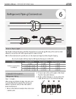
Страница 25: ... m R410A Inverter Split Air Conditioner 15 000 25 82ft 10 33ft 15 000 and 24 000 30 98 5ft 20 66ft 24 000 and 36 000 50 164ft 25 82ft 36 000 and 60 000 65 213ft 30 98 5ft Connection Instructions Refrigerant Piping Step 1 Cut pipes When preparing refrigerant pipes take extra care to cut and flare them properly This will ensure efficient operation and minimize the need for future maintenance 1 Measu...

Страница 26: ...ve all burrs from the cut section of the pipe Pipe Reamer Point down Step 3 Flare pipe ends Proper flaring is essential to achieve an airtight seal 1 After removing burrs from cut pipe seal the ends with PVC tape to prevent foreign materials from entering the pipe 2 Sheath the pipe with insulating material 3 Place flare nuts on both ends of pipe Make sure they are facing in the right direction bec...

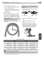
Страница 27: ...Torque N m Ø 6 35 Ø 1 4 1 500 11lb ft 1 600 11 8lb ft Ø 9 52 Ø 3 8 2 500 18 4lb ft 2 600 19 18lb ft Ø 12 7 Ø 1 2 3 500 25 8lb ft 3 600 26 55lb ft Ø 16 Ø 5 8 4 500 33 19lb ft 4 700 34 67lb ft DO NOT USE EXCESSIVE TORQUE Excessive force can break the nut or damage the refrigerant piping You must not exceed torque requirements shown in the table above Instructions for Connecting Piping to Indoor Unit...

Страница 28: ...y as possible by hand 4 Using a spanner grip the body of the valve Do not grip the nut that seals the service valve See Fig 5 10 USE SPANNE R TO GRIP MAIN BOD Y OF VALVE Torque from tightening the flare nut can snap off other parts of valve 5 While firmly gripping the body of the valve use a torque wrench to tighten the flare nut according to the correct torque values 6 Loosen the flaring nut slig...

Страница 29: ...h pressure and low pressure pipes between the indoor and outdoor units are connected properly in accordance with the Refrigerant Piping Connection section of this manual Check to make sure all wiring is connected properly Evacuation Instructions Before using the manifold gauge and vacuum pump read their operation manuals to familiarize yourself with how to use them properly Manifold Gauge Compound...

Страница 30: ...em 11 Removethechargehosefromtheserviceport 12 Using hexagonal wrench fully open both the high pressure and low pressure valves 13 Tighten valve caps on all three valves service port high pressure low pressure by hand You may tighten it further using a torque wrench if needed OPEN VALVE STEMS GENTLY When opening valve stems turn the hexagonal wrench until it hits against the stopper Do not try to ...

Страница 31: ...is detected turn off the unit immediately and call a licensed electrician to find and resolve the cause of the leakage Note This may not be required for some locations in the US Gas Leak Checks There are two different methods to check for gas leaks Soap and Water Method Using a soft brush apply soapy water or liquid detergent to all pipe connection points on the indoor unit and outdoor unit The pr...

Страница 32: ...ton on the remote controller to turn it on 3 Press the MODE button to scroll through the following functions one at a time COOL Select lowest possible temperature HEAT Select highest possible temperature 4 Let each function run for 5 minutes and perform the following checks List of Checks to Perform PASS FAIL No electrical leakage Unit is properly grounded All electrical terminals properly covered...

Страница 33: ...llowing a Using remote control return unit to normal operating temperature b Using insulation tape wrap the indoor refrigerant pipe connections that you left uncovered during the indoor unit installation process IF AMBIENT TEMPERATURE IS BELOW 17 C 63 F You can t use the remote controller to turn on the COOL function when the ambient temperature is below 17 C In this instance you can use the MANUA...

Страница 34: ...ou have the following options Dispose of the appliance at designated municipal electronic waste collection facility When buying a new appliance the retailer will take back the old appliance free of charge The manufacturer will take back the old appliance free of charge Sell the appliance to certified scrap metal dealers Special notice Disposing of this appliance in the forest or other natural surr...

Страница 35: ...Installation Manual DVC DVH 09 12 18 24 Series 34 ...

Страница 36: ... YHULI LQJ GLPHQVLRQDO GDWD RQ WKH DFWXDO SURGXFW SULRU WR EHJLQQLQJ DQ LQVWDOODWLRQ SUHSDUDWLRQV QFHQWLYH DQG UHEDWH SURJUDPV KDYH SUHFLVH UHTXLUHPHQWV DV WR SURGXFW SHUIRUPDQFH DQG FHUWLILFDWLRQ OO SURGXFWV PHHW DSSOLFDEOH UHJXODWLRQV LQ HIIHFW RQ GDWH RI PDQXIDFWXUH KRZHYHU FHUWLILFDWLRQV DUH QRW QHFHVVDULO JUDQWHG IRU WKH OLIH RI D SURGXFW 7KHUHIRUH LW LV WKH UHVSRQVLELOLW RI WKH DSSOLFDQW WR ...

Отзывы: