background image

 3

operation and service

INITIAL PROTECTION AGAINST CORROSION

As shipped, a Marley Geareducer is protected internally against 
corrosion with machine enamel on unmachined parts and with 
rust-proofing oil and grease on machined surfaces. These coatings 
normally protect the Geareducer against atmospheric corrosion for 
storage periods up to six months. However, if oil is added to the 
Geareducer, it will dissolve the rust-proofing grease and oil, requiring 
the Geareducer to be operated once a week to keep a protective 
coating of oil on all interior machined surfaces.
Check Geareducer exterior. If exterior finish has been damaged dur-
ing shipment or installation, touch up with epoxy paint as required. If 
Geareducer is equipped with a remote dipstick/oil level gauge and/or 
drain line, coat any exposed threads at pipe joints to prevent corrosion.

INITIAL OPERATION

The Geareducer must be filled with oil to the full oil level mark on 
the Geareducer case before it is placed in operation. See 

Changing 

Geareducer Oil

 section for oil filling instructions.

Geareducers supplied with new towers include oil for the initial fill-
ing. Oil is not furnished with Geareducers supplied as spares or on 

replacement orders. Before operating the mechanical equipment, 
check to be sure the oil level is at the full mark at the Geareducer 
and that the external gauge placard (if equipped) full mark corre-
sponds with the “Full” level in the Geareducer. Check any oil lines 
to be sure there are no leaks.
Be certain that the vent on the Geareducer (and external dipstick/
oil level gauge, if present) is not plugged.
In order to assure long service life, the Geareducer and motor must 
be level, and the drive shaft or coupling must be properly aligned. 
Refer to the alignment instructions in the Driveshaft or Coupling 
Manual shipped with the cooling tower. Copies are also available 
from your local Marley sales representative.

Note

—If the tower is equipped with a two-speed motor, allow a time 

delay of at least 20 seconds when switching from high speed to 
low speed. Allow a time delay of at least two minutes when chang-
ing direction of fan rotation. Failure to provide these delays may 
significantly reduce equipment service life.

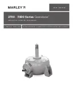
Figure 1 – Service Fittings

VENT

VENT

DRAIN

PLUG

OIL LEVEL

CHECK AND FILL

Содержание 2700-3000 Series

Страница 1: ...2700 3000 Series Geareducer INSTALLATION OPERATION MAINTENANCE user manual uk_Z0529732_A ISSUED 06 2017 READ AND UNDERSTAND THIS MANUAL PRIOR TO OPERATING OR SERVICING THIS PRODUCT ...

Страница 2: ...ng alignment x Inspect and tighten driveshaft or coupling fasteners x Check driveshaft or coupling bushing flex elements for unusual wear x Lube Lines if equipped Check for oil leaks in hoses and fittings x R x R Refer to instructions within this manual Note It is recommended at least weekly that the general operation and condition be observed Pay particular attention to any changes in sound or vi...

Страница 3: ...s Geareducers supplied with new towers include oil for the initial fill ing Oil is not furnished with Geareducers supplied as spares or on replacement orders Before operating the mechanical equipment check to be sure the oil level is at the full mark at the Geareducer and that the external gauge placard if equipped full mark corre sponds with the Full level in the Geareducer Check any oil lines to...

Страница 4: ...k mechanical equipment anchor bolts drive shaft coupling bolts and coupling set screws Tighten as required Check Geareducer exterior yearly and touch up with epoxy paint if required Coat all exposed threads at pipe joints to prevent corrosion Every 5 Years If using Marley synthetic Gearlube change oil To maintain five year change intervals use only Marley Gearlube It is recommended to monitor the ...

Страница 5: ...to a pump to the three way valve operation and service Pump oil through the hose Check oil level occasionally by turning the valve control stem counterclockwise and allowing the oil level in the sight glass to stabilize Continue filling until full level mark is reached 3 With the oil level at the full mark turn the valve control stem counterclockwise to close the drain and open the valve to the si...

Страница 6: ...list 210 502 BEARING RETAINER 203 202 101 301 420 104 105 103 311 503 312 501 PINION CAGE PINION CAGE CAP 320 DOWEL PIN 420 412 201 102 101 008 VENT WATER SLINGER GEAREDUCER CASE 204 411 BOTTOM CAP CASE COVER DOWEL PIN ...

Страница 7: ...4 Tongue Washer 105 Lockwasher 200 Fan Shaft Set 201 Fan Shaft 202 Ring gear hub key 203 Fan key 204 Ring spacer Model 2700 Geareducer only 210 Fan attaching hardware Cap screws and washers 301 Oil Slinger 310 Set of Two Pinion Shaft Bearings 311 Head tapered roller bearing 312 Tail tapered roller bearing 320 Pinion Cage Shims 410 Fan Shaft Bearing Set 411 Lower tapered roller bearing 412 Upper ta...

Страница 8: ... ring of bolts in pinion cage and remove pinion subassembly Note The thickness of the shim pack 320 is important in resetting thegears Theshimpackshouldeitherbesavedorcarefullymeasured with a micrometer If the gears are to be replaced record the pinion setting distance that is etched on the pinion gear See Figure 4 3 Remove water slinger 4 Remove bearing retainer and shim pack 420 from top of case...

Страница 9: ...pinion shaft making sure oil slinger and bearing are against gear 3 Press bearing cups 311 and 312 into pinion cage 4 Lower pinion cage on pinion shaft until head bearing cone and cup mate 5 Press tail bearing cone 312 on pinion shaft until it mates with its bearing cup 6 Install locknut lockwasher and tongue washer 103 105 and 104 Tighten nuts on bearing cone until 8 to 12 in lbƒ 904 1356 mN m of...

Страница 10: ...nthebacklashetchedonthegearset findtheequivalent backlash setting in Table 2 Column 2 2 With the X marked tooth on the pinion gear engaged be tween the two X marked teeth on the ring gear check the backlash with a dial indicator as shown in Figure 5 Lock the pinion shaft against rotation The amount of movement of the fan shaft measured at a distance equal to the outside radius of the ring gear is ...

Страница 11: ...11 field repair Table 2 Backlash Etched on Gears Set the Gears to Backlash 008 010 003 008 009 0115 003 008 010 013 003 008 011 014 004 010 012 015 004 010 013 017 004 010 014 0185 004 010 ...

Страница 12: ...ION In the interest of technological progress all products are subject to design and or material change without notice SPX COOLING TECHNOLOGIES UK LTD 3 KNIGHTSBRIDGE PARK WORCESTER WR4 9FA UK 44 1905 750 270 ct fap emea spx com spxcooling com Geareducer US E R MAN UAL ...

Отзывы: