Mark Levinson ?585 Скачать руководство пользователя страница 11

9

N

0

585 INTEGRATED AMPLIFIER


/


QUICK-START GUIDE

GETTING STARTED

NOTE: 

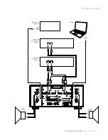
For complete information about the remote 

control functions, see the 

N

0

585 User Guide. at www.

marklevinson.com.

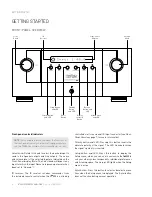
Standby button: Press this button to put the N

0

585 into and 

out of the Standby mode. 

Select buttons: Press these buttons to select the desired 
input. The name and volume level of the selected input are 
indicated on the front-panel display.

/– buttons: Press these buttons to adjust the 
volume  level  of the Speaker outputs (and of the Line 
outputs if you have set them to 

Variable in the Setup menu). 

The minimum volume level is OFF; the maximum volume 
level is determined in the Setup menu.

Whenever you select an input, the N

0

585 applies the volume 

offset selected for it in the Setup menu to the Main output 
volume  level  (and to the Line output volume level if you 
have set it to 

Variable in the Setup menu).

Setup button: Press this button to display the Setup menu, 
which you can use to customize the N

0

585 to suit your 

individual preferences, listening space and other system 
components. The Setup LED on the front panel illuminates 
when the Setup menu is active. 

Mute button: Press this button to mute and unmute the 
level of the speaker outputs (and the Line outputs, if you 
have set them to 

Variable in the Setup menu) by the amount 

determined in the Setup menu. The Mute LED on the front 

panel lights when the mute function is active.

Enter button: Press this button to select or deselect a 
menu item when the Setup menu is displayed. 

Balance buttons: Press this button to set the left-to-right 
channel balance. The Balance LED illuminates when the 
balance function is active. (It also remains illuminated 
when the balance function is inactive if the left-to-right 
channel balance is offset.)

Clari-Fi button: Pressing this button activates the Clari-Fi 
circuitry. Clari-Fi analyzes compressed digital audio files 
during playback and “rebuilds” much of what was lost in 
compression. (Clari-Fi functions only when a digital input 
is the active input.)
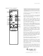
Standby

Button

Select

Buttons

Setup

Button

Volume
Buttons

Mute
Button

Balance
Button

Display
Button

USB
Control
Buttons

Enter

Button

Clari-Fi

Button

Polarity

Button

REMOTE CONTROL OVERVIEW

Содержание ?585

Страница 1: ...INTEGRATED AMPLIFIER QUICK START GUIDE N0 585...

Страница 2: ......

Страница 3: ...ons Troubleshooting 14 Specifications 15 This quick start guide contains all the information you will need to unpack your N0 585 connect it to the rest of your audio system turn it on and have a first...

Страница 4: ...g and initial setup 1 xN0 585 Quick Start Guide NOTE The N0 585 User Guide is available for download online at www marklevinson com Please register your N0 585 within 15 days of your purchase Register...

Страница 5: ...operating with the same solid low impedance ground reference You should unplug the N0 585 from the AC wall outlet during lightning storms and extended periods of non use CAUTION BEFORE moving the N0...

Страница 6: ...hen the N0 585 is not being controlled via its rear panel IR Input connector see Rear Panel Overview page 7 for more information Polarity button and LED Pressing this button inverts the absolute polar...

Страница 7: ...have set them to Variable in the Setup menu by the amount determined in the Setup menu The LED lights when the mute function is active Front Panel display This 16 character alphanumeric display provid...

Страница 8: ...ut Connector Trigger Input Connector Trigger Output Connector USB Digital Connector AC Mains Connector Ethernet Port USB Port Right Channel Line Output Connector Right Channel Balanced Analog Input Co...

Страница 9: ...components or a second audio zone When configured as Fixed the Line outputs are not affected by any of the N0 585 s front panel controls except for the Polarity button If your system includes a powere...

Страница 10: ...put connector This 3 5mm tip sleeve connector can be connected to the trigger output of another system component or control system that supplies a trigger voltage Whenever the N0 585 detects a voltage...

Страница 11: ...ividual preferences listening space and other system components The Setup LED on the front panel illuminates when the Setup menu is active Mute button Press this button to mute and unmute the level of...

Страница 12: ...nt panel illuminates when the signal s polarity is inverted Display button Press this button to change the intensity of the N0 585 s front panel display characters and its front panel LEDs Multiple pr...

Страница 13: ...R receiver Make sure that no objects such as furniture block the remote s view of the receiver Bright lights fluorescent lights and plasma video displays may interfere with the function of the remote...

Страница 14: ...balanced XLR connectors and three sets of single ended RCA connectors are available 4 Connect up to six digital source components to the N0 585 s digital audio inputs One AES EBU XLR connector two co...

Страница 15: ...ATED AMPLIFIER QUICK START GUIDE QUICK SETUP AND LISTEN Balanced Analog Source Component Single Ended Analog Source Component Digital Source Component Computer To Digital Output To USB Port Right Spea...

Страница 16: ...es not clear call your Mark Levinson dealer or Mark Levinson customer service WARNING OVER TEMP LEFT RIGHT Indicated amplifier channel has exceeded thermal limits Put the N0 585 into standby by pressi...

Страница 17: ...air single ended line outputs RCA 1 pair loudspeaker outputs Hurricane binding posts w banana sockets that accept spade lugs with 1 4 6 3mm spacing up to 1 8 3mm thick Digital Audio Connectors 1 balan...

Страница 18: ...hich they are associated This document should not be construed as a commitment on the part of HARMAN International Industries Incorporated The information it contains as well as the features specifica...

Отзывы: