background image

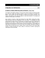
STANDARD SYSTEM OPERATING CHARACTERISTICS, 5 hp & 10 hp

The system uses special cylinders to move the ram and two timers to control the opera-
tion of the ram. When the hydraulic cylinders used in the RJ-88SC, RJ-100SC, RJ-
250SC, and RJ-250VL are fully extended or retracted, they bypass internally. This
makes it impossible for the hydraulic system to reach relief pressure. The sequence of
operation for this system is as follows:

Upon startup, a contact is made that energizes the motor starter, starting the electric
motor and at the same time energizing T1 timer coil. When T1 is energized, the valve
solenoid shifts the valve so that  the hydraulic oil is directed to extend the cylinder which
extends the ram. When T1 timer times out, the contacts reverse causing T2 timer  to
energize and the solenoid to shift the valve into the reverse position. In this position, the
valve directs the hydraulic oil into the front end of the cylinder causing the cylinder to
retract, therefore causing the ram to retract. When T2 timer times out, the motor starter
contact is opened causing the motor starter to shut down, therefore causing the
motor/power unit to shut down.

2  MAINTENANCE

PRINCIPLES OF OPERATION

2-6

Содержание RJ-100SC

Страница 1: ...FOR RJ 88SC RJ 100SC RJ 250SC RJ 250VL Includes HT Hydraulic Tailgate Units and SL StreamLine Liquid Removal Units RAM JET SELF CONTAINED COMPACTOR CONTAINER VERNON AL FAYETTE AL YERINGTON NV CLEARFIE...

Страница 2: ...s Cylinder Removal Multi Cycle Timer Adjustment 2 5 Principles of Operation 2 6 Tailgate Seal Replacement 2 7 Charts 2 8 Parts List 2 10 Motor Control Panel 2 11 Power Unit Standard 5 HP 2 12 Power Un...

Страница 3: ...ing applicable standards ANSI Standard No Z245 2 Stationary Compactors Safety Requirements A copy of this standard may be obtained from ENVIRONMENTAL INDUSTRIES ASSOCIATION 4301 Connecticut Avenue NW...

Страница 4: ...op Opening 30 1 2 x 48 35 x 60 40 5 x 58 35 x 60 L x W B 70 76 1 8 68 76 1 2 C 42 49 5 8 52 1 2 51 1 2 D max 96 104 104 104 E max 254 1 2 276 275 288 Charge Box Capacity 1 00 1 50 1 90 1 90 cubic yard...

Страница 5: ...RVICING Only authorized service personnel should be allowed inside All access doors on the compactor body should always be secured in place when the unit is operating See Lock Out Tag Out instructions...

Страница 6: ...ssed The Keyed Start Switch must be energized for the REVERSE button to operate See the MANUAL OVERRIDE INSTRUCTIONS on the next page for details of the operation 1 2 3 CONTROL DESCRIPTION FOR 88SC 10...

Страница 7: ...r has stopped When you have finished using the compactor remove the key from the key switch IN CASE OF EMERGENCY Push the large red button to STOP MANUAL OVERRIDE INSTRUCTIONS RAM STOP REAR ONLY 88SC...

Страница 8: ...When you have finished using the compactor remove the key from the key switch IN CASE OF EMERGENCY Push the large red button to STOP MANUAL OVERRIDE INSTRUCTIONS RAM STOP REAR ONLY RJ 250VL If the ra...

Страница 9: ...his option has been stopped the ram automatically begins to move rearward when restarted For the RJ 88SC RJ 100SC or RJ 250SC to move the ram forward when it is stopped hold the FORWARD button down tu...

Страница 10: ...s CAUTION STAND CLEAR WHEN CONTAINER IS BEING LIFTED A PORT B PORT CAUTION DO NOT REMOVE THIS CONTAINER UNTIL REAR STOP IS INSTALLED QUICK CLEAN TANK FIRE HOSE PORT NOTICE WIPE OFF SEAL AFTER DUMPING...

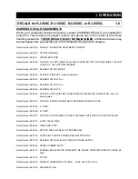
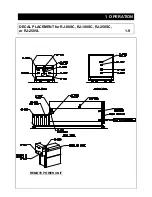
Страница 11: ...1 OPERATION DECAL PLACEMENT for RJ 88SC RJ 100SC RJ 250SC or RJ 250VL 1 9 REMOTE POWER UNIT...

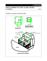
Страница 12: ...S 1 OPERATION 06 0040 ACCESS GATE HOPPER EACH OUTSIDE WALL DOCK 06 0039 06 0039 06 0039 06 0052 EACH INSIDE WALL DOGHOUSE THRU THE WALL SECURITY CHUTE 06 0039 06 0039 DECAL PLACEMENT for RJ 88SC RJ 10...

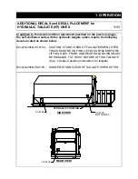
Страница 13: ...e the following decals located as shown below Decal Number 06 0104 CAUTION STAND CLEAR OF TAILGATE WHEN LIFTED TRUCK MUST BE ON FIRM LEVEL SURFACE BEFORE LIFTING GATE FRONT AND REAR HOLD DOWNS MUST BE...

Страница 14: ...ovided as minimum guidelines 2 MAINTENANCE HYDRAULIC Stored hydraulic energy must be removed from the compactor hydraulic cir cuit for complete lock out and tag out Make sure that this energy has been...

Страница 15: ...e and lifting the fil ter from the reservoir Care should be exercised in cleaning the fiIter to insure that the element is not torn Clean the element with a soft brush and standard industrial solvent...

Страница 16: ...hoses disconnected the power unit will build pressure Adjust the relief pressure up by turning the relief adjustment screw clockwise Adjust the relief valve to the desired pressure setting and tighte...

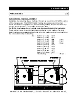
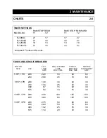
Страница 17: ...s time passes the cycle time may change and need to be readjusted To set a timer move the appropriate binary switches to the ON position The timer switch settings are cumulative all switches in the ON...

Страница 18: ...solenoid wire from terminal 8 to terminal 10 Reset timers by the settings shown in the TIMER SETTINGS section under CHARTS in this manual Change the START FORWARD key lock push button legend to START...

Страница 19: ...g the electric motor and at the same time energizing T1 timer coil When T1 is energized the valve solenoid shifts the valve so that the hydraulic oil is directed to extend the cylinder which extends t...

Страница 20: ...SEAL S WHEN REMOVING THE OLD SEALS TOP BOTTOM MARK THE POSITION OF THE SEAL JOINTS PRY THE SEAL RETAINER UP SLIGHTLY TO ALLOW REMOVAL OF THE OLD SEALS WHEN INSTALLING THE NEW SEALS JOIN THE SEALS AT T...

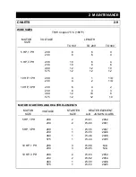
Страница 21: ...units FUSES AND CIRCUIT BREAKERS MOTOR FULL DUAL ELEMENT CIRCUIT SERVICE SIZE VAC LOAD FUSE BREAKER DISCONNECT AMP MAX SIZE MAX SIZE AMP 5 HP 1 PH 208 22 0 50 80 60 230 20 8 45 70 60 5 HP 3 PH 208 13...

Страница 22: ...2438 575 1 W 44 2435 10 HP 1 PH 208 3 W 66 N A 230 3 W 65 N A 10 HP 3 PH 208 2 W 63 2454 230 2 W 62 2454 460 1 W 55 2446 575 1 W 53 2445 CHARTS 2 9 WIRE SIZES THW Copper 75 C 165 F MOTOR VOLTAGE LENG...

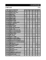
Страница 23: ...0195 SWITCH KEYLOCK START X X X X X 03 0196 SWITCH MUSHROOM STOP X X X X X 03 0197 SWITCH BLACK REVERSE X X X X X 03 0288 TRANSFORMER X X X X X X 03 0345 MOTOR 10 HP X X X X 03 0458 P C BOARD X X X X...

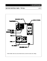
Страница 24: ...2 MAINTENANCE MOTOR CONTROL PANEL TYPICAL 2 11 Motor Starter brand and size determined by model number and voltage...

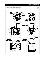
Страница 25: ...2 MAINTENANCE POWER UNIT STANDARD 5 HP 2 12 DETAIL B DETAIL A DETAIL A DETAIL B DRAIN PLUG...

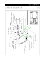
Страница 26: ...2 MAINTENANCE POWER UNIT STANDARD 10 HP 2 13...

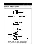
Страница 27: ...2 MAINTENANCE HYDRAULIC SCHEMATIC TYPICAL 2 14 SINGLE CYLINDER UNIT SHOWN FOR DUAL CYLINDER UNITS CONNECT IDENTICAL CYLINDER IN PARALLEL...

Страница 28: ...loses when depressed 3A Check heater resets 1A Check motor starter coil wiring 2A Check motor starter contacts and wiring 3A Check reverse button to be sure contacts are closed 3B Check wiring 4A Chec...

Страница 29: ...is adequate to remove sys tem generated heat 1B Install oil cooler air or water type 1C Install oil temperature shut down switch 1D Check to be sure CYCON Power Pack has not been exchanged for Pressu...

Страница 30: ...that the concrete pad be flush with the surrounding ground level NOTE Units with four ground rollers must be installed on a level pad To provide accessibility concrete pad should be positioned to allo...

Страница 31: ...k placement See ANSI Z245 2 Safety Standards Optional container guides with stops are available from Marathon and are recommended for proper dock placement of the compactor container 3 INSTALLATION ST...

Страница 32: ...be located so that the Mushroom Emergency Stop Button is readily accessible to the operator and within three 3 feet of the charging chamber access door If installation requires the operator station t...

Страница 33: ...etermine the proper service disconnect amperage rating and the proper wire size NOTE High legs should be installed to L3 on motor starter Check voltage at fused disconnect switch to be certain it is t...

Страница 34: ...Hose Hi Pressure sized to power unit 36 long 2 2 Pipe Sch 80 sized to power unit 36 long 3 2 Hydraulic Hose Hi Pressure sized to power unit 48 long 4 2 Steel plate with holes for Item No 2 3 16 x 8 x...

Страница 35: ...ctrical connections if applic able to the compactor Make sure they are not laying across sharp corners or any abrasive surface Close and secure any hopper doors or gates Make sure that the container d...

Страница 36: ...E CONTAINER FLOOR AUTO RELATCH AUTO RELATCH IN POSITION TO OPEN DOOR AUTO RELATCH IN POSITION TO GRAB AND HOLD DOOR DURING DOOR CLOSING ROTATE THE AUTO RELATCH UP TO THE POSITION SHOWN AND OPEN THE LA...

Страница 37: ...ON DISENGAGE LATCH EACH SIDE 3 4 5 RAISE HOIST LIFT TAILGATE EMPTY CONTENTS 6 7 8 9 10 11 CLEAN SEAL AS DESCRIBED IN THE HAULER INSTRUCTIONS GENERAL IN THIS SECTION OF THE MANUAL NOTE WARNINGS LOWER T...

Страница 38: ...pin from maintenance bar and slide bar toward compactor 3 Align holes in the position collar and bar and insert pin 4 Use a mop or similar cleaning device with a long handle to clean the seal 5 Raise...

Страница 39: ...oved to any of the four drain outlets on the machine The valve should be located at the lowest outlet on the machine for proper drainage The customer can attach a drain hose with a 3 NPT male fitting...

Отзывы: