background image

14

ENGLISH

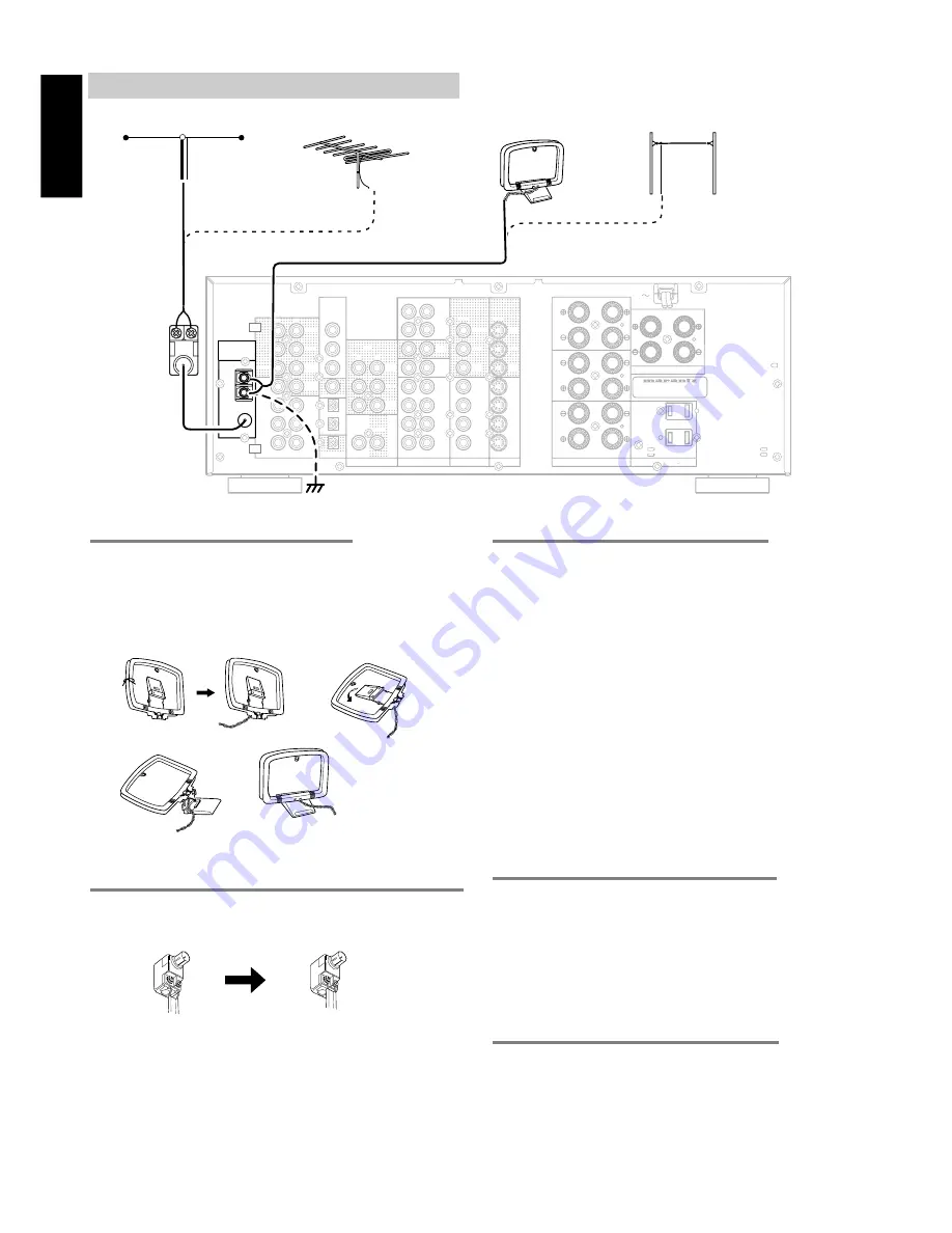
CONNECTING THE ANTENNA TERMINALS

ASSEMBLING THE AM LOOP ANTENNA

1.

Release the vinyl tie and take out the connection line.

2.

Bend in the reverse direction.

3.

Inserting into the hole to attach the loop antenna to the antenna
stand.

4.

With the antenna on top any stable surface.

CONNECTING THE ANTENNA CABLE TO THE 75/300 

 ANTENNA ADAPTER

Connecting the 300 

 ribbon wire

Loosen the screws and wrap the wire around these screws.
Then tighten the screws with a screwdriver.

CONNECTING THE SUPPLIED ANTENNAS

Connecting the supplied FM feeder antenna

The supplied FM feeder antenna is for indoor use only.
During use, extend the antenna and move it in various directions until
the clearest signal is received.
Fix it with push pins or similar implements in the position that will
cause the least amount of distortion.
If you experience poor reception quality, an outdoor antenna
may improve the quality.

Connecting the supplied AM loop antenna

The supplied AM loop antenna is for indoor use only.
Set it in the direction and position where you receive the clearest
sound.  Put it as far away as possible from the unit, televisions,
speaker cables, and power cords.
If you experience poor reception quality, an outdoor antenna may
improve the quality.

1.

Loosen the AM antenna terminal screw counterclockwise.

2.

Insert the bared wire into the antenna terminal.

3.

Tighten the screw by turning clockwise to secure the wire

CONNECTING AN FM OUTDOOR ANTENNA

NOTES

• Keep the antenna away from noise sources (neon signs, busy

roads, etc.).

• Do not put the antenna close to power lines.  Keep it well away

from power lines, transformers, etc.

• To avoid the risk of lightning and electrical shock, grounding is

necessary.

CONNECTING AN AM OUTDOOR ANTENNA

An outdoor antenna will be more effective if it is stretched
horizontally above a window or outside.

NOTES

• Do not remove the AM loop antenna.
• To avoid the risk of lightning and electrical shock, grounding is

necessary.

1.

3.

4.

2.

(75

)

GND

AM

FM

AUDIO

CENTER

REMOTE CONTROL

OUT

CENTER

SURR.

CENTER

SURR.

L

R

CENTER

SURR.CENTER

SURROUND

FRONT

TOR

MONI

S


-


VIDEO

VIDEO

OUT

VCR2

DSS /

VCR2

DSS /

VCR1

VCR1

MONITOR

VCR2

DSS /

TV

DVD

VCR1

IN

TV

VCR1

DVD

VCR2

DSS /

IN

TV

VCR1

DVD

VCR2

DSS /

IN

TAPE

TAPE

/ MD

CDR 

CD

R

L

IN

VCR2

DSS /

VCR1

OUT

R

L

IN / OUT

DIGITAL

DIG.OUT OPT

DIG - 1  IN

DIG - 2  IN

DIG.OUT COAX

DIG - 3  IN

DIG - 4  IN

FRONT

SURR.

CENTER

SURR.

FRONT

WOOFER

SUB 

WOOFER

SUB 

R

L

R

L

OUT

PRE

INPUT

6.1CH

ANTENNA

DIG - 5  IN

/ MD

CDR 

MODEL NO. SR6300 

OUT

L

R

L

R

SPEAKER SYSTEMS  A

120W 1A MAX

UNSWITCHED

120W 1A MAX

SWITCHED

AC OUTLETS

(120V    60Hz)

SPEAKER SYSTEMS  B

(75

)

GND

AM

FM

ANTENNA

FM FEEDER

ANTENNA

FM EXTERNAL

ANTENNA

AM LOOP

ANTENNA

AM EXTERNAL

ANTENNA

Содержание SR6300

Страница 1: ...Model SR6300 User Guide AV Surround Receiver R ...

Страница 2: ... proper grounding and in particular specifies that the cable ground shall be connected to the grounding system of the building as close to the point of cable entry as practical NOTE This equipment has been tested and found to comply with the limits for a Class B digital device pursuant to Part 15 of the FCC Rules These limits are designed to provide reasonable protection against harmful interferen...

Страница 3: ... may be equipped with a polarized alternating current line plug a plug having one blade wider than the other This plug will fit into the power outlet only one way This is a safety feature If you are unable to insert the plug fully into the outlet try reversing the plug If the plug should still fail to fit contact your electrician to replace your obsolete outlet Do not defeat the safety purpose of ...

Страница 4: ...eplacement Parts When replacement parts are required be sure the service technician has used replacement parts specified by the manufacturer or have the same characteristics as the original part Unauthorized substitutions may result in fire electric shock or other hazards 23 Safety Check Upon completion of any service or repairs to this product ask the service technician to perform safety checks t...

Страница 5: ... IN TV DVD VCR1 VCR2 DSS OUT TAPE TAPE MD CDR CD R L IN VCR2 DSS VCR1 OUT R L IN OUT DIGITAL DIG OUT OPT DIG 1 IN DIG 2 IN DIG OUT COAX DIG 3 IN DIG 4 IN FRONT SURR CENTER SURR FRONT WOOFER SUB WOOFER SUB R L R L OUT PRE INPUT 6 1CH ANTENNA DIG 5 IN L R MD CDR MODEL NO SR6300 120W 1A MAX UNSWITCHED 120W 1A MAX SWITCHED AC OUTLETS 120V 60Hz SPEAKER SYSTEMS B ATT PEAK NIGHT DISPLAY OFF HT EQ A SLEEP...

Страница 6: ...NNECTING THE ANTENNA TERMINALS 14 SETUP 15 ON SCREEN DISPLAY MENU SYSTEM 15 INPUT SETUP ASSIGNABLE DIGITAL INPUT 16 SPEAKER SETUP 16 PREFERENCE 18 SURROUND 18 PL2 PRO LOGIC II MUSIC PARAMETER 18 CS2 CIRCLE SURROUND II PARAMETER 19 6 1 CH INPUT LEVEL 19 BASIC OPERATION 20 LISTENING TO THE TUNER 20 PLAYBACK OPERATION 21 TV AUTO ON OFF FUNCTION 21 SETTING THE SLEEP TIMER 22 ADJUSTING THE SURROUND LEV...

Страница 7: ...ofessionally in movie theaters since 1999 In addition to the 5 1 surround channels FL FR C SL SR and LFE DTS ES Extended Surround also offers the SC Surround Center channel for surround playback with a total of 6 1 channels DTS ES Extended Surround includes two signal formats with different surround signal recording methods as DTS ES Discrete 6 1 and DTS ES Matrix 6 1 DTS DTS ES Extended Surround ...

Страница 8: ...rectionality on Dolby Surround program material and provides a convincing three dimensional sound field on conventional stereo music recordings DTS NEO6 DTS Neo6 decoder built in to decode 6 1 channel surround sound from any stereo material CIRCLE SURROUND II CIRCLE SURROUND II decoder built in to decode 6 1 channel surround sound from any stereo or passive matrix encoded material SOURCE DIRECT MO...

Страница 9: ...d the tone control circuit is bypassed as well as Bass Management Notes The surround mode is automatically switched to AUTO when the source direct function is turned on Additionally Speaker Configurations are fixed automatically as follow Front SPKR LARGE Center SPKR LARGE Surround SPKR LARGE Surround Center SPKR YES Sub woofer YES S DIRECT is turned off when the other surround mode is selected wi...

Страница 10: ...o the front left right speakers Notes When you use the speaker systems A and B simultaneously the connected speakers which are impeadance 12 to 16 ohms must be used l 6 1 CH INPUT jacks Connect to the outputs of DVD Audio player SACD Multi channel player or an external multichannel decoder 0 DIGITAL outputs Optical and Coaxial Connect to the digital input of your digital recording equipment 1 DIGI...

Страница 11: ...eaker The BASS buttons are used to adjust the tone control of low frequency sound for left right and subwoofer speaker Deck cotrol buttons when Tape mode is selected The DECK A button are used to select the deck A The DECK B button are used to select the deck B The 1 2 button are used to change the direction 5 CURSOR OK button Used to operate on screen and other displays used by receivers and othe...

Страница 12: ... according to their genre into different programme type PTY groups Note This button is unavailable for SR6300 9 F DIR SEAR button when TUNER mode is selected Used to select the mode of frequency direct input 0 DISP RDS button when TUNER mode is selected Selects display mode function in RDS Radio Data System by this button Note This button is unavailable for SR6300 when AMP mode is selected When th...

Страница 13: ...or button Please refer as below for the details in AMP mode POWER ON OFF Turns the SR6300 on and off POWER ON Turns the SR6300 on POWER OFF Turns the SR6300 off EQ Turns on or off HT EQ mode 7 1 6 1 IN Selects the 6 1CH IN SLEEP Sets the sleep timer function A D Switches between the analog and digital inputs DISP RDS Changes the brightness of the front display Surround mode Selects the surround mo...

Страница 14: ...rs however they may be used in place of a subwoofer with proper setting of the switches in the menu system Front left and right speakers We recommend to set the front L and R speakers with 45 60 degrees from the listening position Center speaker Align the front line of the center speaker with the front L R speakers Or place the center speaker a little backward from the line Surround left and right...

Страница 15: ... be corrupted CONNECTING A SUBWOOFER Use the PRE OUT SUBWOOFER jack to connect a powered subwoofer power amplifier built in If your subwoofer is passive type power amplifier is not built in connect a monaural power amplifier to the PRE OUT SUBWOOFER jack and connect the subwoofer to the amplifier 1 2 3 4 5 3 8 inch 10 mm 75Ω GND AM FM AUDIO CENTER REMOTE CONTROL OUT CENTER SURR CENTER SURR L R CEN...

Страница 16: ...structions for each component that is connected with this unit Do not bind audio video connection cables with power cords and speaker cables will result in generating hum or other noise CONNECTING DIGITAL AUDIO COMPONENTS There are four digital inputs two coaxial jacks and two optical jacks on the rear panel You can use these jacks to input PCM Dolby Digital and DTS bitstream signals from a CD DVD...

Страница 17: ... VIDEO OUT L R AUDIO OUT AUDIO IN L R VIDEO OUT IN S VIDEO OUT IN DIGITAL OUT L R L R L R L R L R L R L R CONNECTING VIDEO COMPONENTS VIDEO S VIDEO JACKS There are two types of video jacks on the rear panel VIDEO jack The video signal for the VIDEO jacks is the conventional composite video signal S VIDEO jack The video signal is separated into luminance Y and color C signals for the S VIDEO jack T...

Страница 18: ... with the remote controller by connecting REMOTE CONTROL terminals on each unit The signal transmitted from the remote controller is received by the remote sensor on this unit then the signal is sent to the connected device through this terminal Therefore you need to aim the remote signal only to the unit Also if a Marantz power amplifier some models excluded is connected with this terminal the po...

Страница 19: ... improve the quality 1 Loosen the AM antenna terminal screw counterclockwise 2 Insert the bared wire into the antenna terminal 3 Tighten the screw by turning clockwise to secure the wire CONNECTING AN FM OUTDOOR ANTENNA NOTES Keep the antenna away from noise sources neon signs busy roads etc Do not put the antenna close to power lines Keep it well away from power lines transformers etc To avoid th...

Страница 20: ...u system press EXIT button or move the cursor to EXIT and press the OK button SE TUP MA I N MENU 1 I NPUT SE TUP UNLOCK 2 SP EAKER S E TUP UNLOCK 3 PRE F ERENCE UNLOCK 4 SURROUND UNLOCK 5 PRO LOG I C 2 UNLOCK 6 CS 2 UNLOCK 7 6 1 CH I N UNLOCK E X I T 1 I NPUT SE TUP CD D I G 3 T V ANA TAP E ANA DVD D I G4 CD R D I G 1 VCR 1 ANA DSS D I G2 MA I N E X I T 2 1 SP EAKERS S I Z E SUBWOOF ER YES FRONT L...

Страница 21: ...z will be output from the subwoofer If the Subwoofer is set to NONE and the front speakers are set to LARGE then the sound may be output from both the left and right speakers 1 Select SPEAKER SETUP in MAIN SETUP MENU with or cursor button and press the OK button 2 To select the each speaker press or cursor button 1 I NPUT SE TUP CD D I G3 T V ANA TAP E ANA DVD D I G4 CD R D I G1 VCR 1 ANA DSS D I ...

Страница 22: ... that you selected NONE for in the Speaker Size menu will not appear SPEAKERS LEVEL Here you will set the volume for each speaker so that they are all heard by the listener at the same level Note The speaker level settings is not available in 6 1channel input mode and S Direct mode TEST MODE Selects MANUAL or AUTO for generating mode of test tone or cursor button If you select AUTO the test tone w...

Страница 23: ...EX I T SUB W Adjust the volume level of the subwoofer speaker between 15 dB and 10 dB in 1 level interval with or cursor button If you finish the setup in this item move cursor to MAIN with or cursor buttons and press OK button Note CENTER SURR R SURR C SURR L and SUB W volume level are synchronized with SETUP MAIN MENU 2 3 Speaker Level PL2 PRO LOGIC II MUSIC PARAMETER Pro Logic II Music mode cre...

Страница 24: ... then this setting will not appear If you finish the setup in this menu move cursor to MAIN with or cursor buttons and press OK button 6 1 CH INPUT LEVEL This sub menu is to adjust the speaker levels for 6 1 channel input sources Here you will adjust the volume for each channel so that they are all heard by the listener at the same level 1 Select 6 1CH IN in SETUP MAIN MENU with or cursor button a...

Страница 25: ...o Presetting This function automatically scans the AM and FM band and enters all stations with sufficient signal strength into the memory 1 Press and hold down the MEMORY button 3 and TUNER button t simultaneously auto presetting will start 2 MEMO will blink on the display 3 Each time the tuner finds a station the scanning will pause and memory Auto presetting will starts 4 Operation stops automat...

Страница 26: ...MO button 6 for more than 1 second to confirm the entry PLAYBACK OPERATION NORMAL PLAYBACK 1 Press the POWER button q 4 2 Press the desired FUNCTION SELECTOR button t on the front panel or press the desired FUNCTION button 9 on the remote unit to select an input source 3 Turn the SURROUND MODE SELECTOR knob e on the front panel or Surround mode buttons in the AMP MODE on the remote unit to select ...

Страница 27: ...y shows to SLEEP OFF and the SLEEP indicator disappear ADJUSTING THE SURROUND LEVEL Adjust the volume level of speakers depend on your preference 1 Press the CH SEL button 6 in the AMP mode on the remote controller SURROUND will be displayed 2 To select a desired speaker channel with or cursor button 3 Adjust the volume level of speaker with press or cursor buttons 4 To exit from surround menu pre...

Страница 28: ...d the TV MONI S Video output jacks When you connect both the composite video and S VIDEO there will be no signal output from composite video jack With some video equipment or software the On Screen Display characters may be distorted due to noise or tracking adjustment error 2 FUCTION SELECT SURROUND MODE When a function selector button or surround mode button is pressed VIDEO Displays the current...

Страница 29: ...and off POWER ON Turns the DVD player on POWER OFF Turns the DVD player off Opens closes the disc tray AUDIO Selects the audio language ANGLE Selects the camera angle SUBTITLE Selects the subtitle language 0 9 10 Inputs the numeric DISP Displays the disc information F DIR SEAR Searches the title or track CL Clears the inputting MEMO Calls up progamming menu DECK A Next disc tray TOP MENU Calls up ...

Страница 30: ...the numeric CL Clears the inputting MEMO Programes MENU OSD Switches the display information 4 Skips forward or previous track 5 6 Seachs forward or backward 0 Record Pause 9 Stop 2 Play POWER ON OFF Turns the tape deck on and off POWER ON Turns the tape deck on POWER OFF Turns the tape deck off Eject the tape 0 9 Inputs the numeric CL Clears the inputting MEMO Programes DECK A B Changes the tape ...

Страница 31: ...ished programming the remote controller press and hold down the OK button 5 until USE is displayed in the display Note When NG is displayed in step 5 again the transmitting code is unavailable for RC7300SR or the transmitting signal is intercepted by noise If no buttons are pressed for approximatelly 1 minutes while in the LEARN mode the remote controller automatically returns to the use mode ERAS...

Страница 32: ...e up a macro are set initially to be sent one after another in 1 second intervals however these intervals may be shortened to as little as 0 5 seconds or lengthened to as much as 5 seconds using the Setup mode In the macro mode the number of steps the macro is displayed the following selected function name Macros may be programmed for each of the 12 function buttons as follows TV DVD VCR1 DSS TUNE...

Страница 33: ...layed on the LCD Also the step numbers displayed on LCD a disappear as each step is executed 2 After all macro commands have been transmitted the remote controller returns to AMP in use mode 4 When you are finished programming macros press and hold the OK button 5 until the display returns to USE mode Macros cannot be programmed for the MEMO 6 cursor OK 5 VOL 3 or CL buttons In the macro mode it i...

Страница 34: ...macro commands are transmitted in order and the steps of the operations are displayed on LCD in order When executing this macro function operations AMP and DVD only switch the command set of the remote controller and no signal is transmitted to the component EXAMPLES OF MACRO PROGRAMS Example 1 Change the input source for the amplifier to CD and play the 3rd track on a CD in the CD player 1 Press ...

Страница 35: ...d in the display CLEARING MACRO PROGRAMS The following procedure is used to erase macros you have programmed into the remote controller s memory 1 Press and hold the T MODE 1 and MENU button 2 until the MACRO is displayed on the LCD LEARN and MACRO is displayed blinking 2 Press and hold the CL button then the button for the function to be cleared in this case DVD for 3 seconds DVDCL will appear on...

Страница 36: ...ra channel which has been added during the mixing of the program This channel called Surround Center places sounds behind the listener in addition to the currently available front left front center front right surround right surround left and subwoofer channels This additional channel provides the opportunity for more detailed imaging behind the listener and brings more depth spacious ambience and...

Страница 37: ...s from certain CD players and LD players even if you connect the player to the SR6300 digitally This is because the digital signal has been processed such as the output level sampling frequency or frequency response and the SR6300 cannot recognize the signal as DTS data Depending on the player used DTS play may produce short noise This is not a malfunction In such cases select the surround mode th...

Страница 38: ...OLBY DIGITAL 2CH Lt Rt O O O O DOLBY DIGITAL PRO LOGIC DOLBY PL DOLBY DIGITAL EX 6 1CH O O O O DOLBY DIGITAL DOLBY D 96KHZ PCM PCM AUDIO O O O O DOLBY PRO LOGIC PCM DOLBY PL ANALOG O O O O DOLBY PRO LOGIC DOLBY PL DTS 5 1CH DTS ES 6 1CH EX ES DOLBY DIGITAL 5 1CH O O O O O DOLBY DIGITAL SURROUND EX DOLBY D EX DOLBY DIGITAL 2CH DOLBY DIGITAL 2CH Lt Rt DOLBY DIGITAL EX 6 1CH O O O O O DOLBY DIGITAL S...

Страница 39: ... O O O O DSP SOUND MOVIE or HALL or STADIUM or MATRIX DTS 5 1CH DTS ES 6 1CH STEREO DOLBY DIGITAL 5 1CH O O STEREO DOLBY DIGITAL STEREO DOLBY DIGITAL 2CH O O STEREO DOLBY DIGITAL STEREO DOLBY DIGITAL 2CH Lt Rt O O STEREO DOLBY DIGITAL STEREO DOLBY DIGITAL EX 6 1CH O O STEREO DOLBY DIGITAL STEREO 96KHZ PCM O STEREO PCM STEREO 96KHz PCM AUDIO O O STEREO PCM STEREO ANALOG O O STEREO STEREO DTS 5 1CH ...

Страница 40: ...n Cannot get programmed station when the PRESET button is pressed Control with the remote control unit fails REMEDY Connect the power plug to the outlet Cancel mute using the remote control unit See the connection diagram and connect the cables correctly Adjust the master volume Select correct position Disconnect the headphones Speakers will not output sound when headphones are connected Connect t...

Страница 41: ...e SR6300 is equipped with a backup function to prevent memory data such as the preset memory from being erased The memory functions are backed up for up to about one week Note First of all keep SR6300 Standby or Powered on more than 6 hours to sufficient time for memory back up HOW TO RESET THE UNIT Should the operation or display seem to be abnormal reset the unit with the following procedure 1 T...

Страница 42: ...SECTION Power Output 20 Hz 20 kHz THD 0 08 Front L R 8 ohms 100 W Ch Center 8 ohms 100 W Ch Surround L R 8 ohms 100 W Ch Surround Center 8 ohms 100 W Ch Front L R 6 ohms 125 W Ch Center 6 ohms 125 W Ch Surround L R 6 ohms 125 W Ch Surround Center 6 ohms 125 W Ch Input Sensitivity Impedance Linear 340 mV 47 Kohms Signal to Noise Ratio Linear 105 dB DIMENSION VIDEO SECTION Television Format NTSC Inp...

Страница 43: ...SIA Wo Kee Hong Electronics Sdn Bhd Suite 8 1 Level 8 Menara Genesis No 33 Jalan Sultan Ismail 50250 Kuala Lumpur Malaysia MALTA Doneo Co Ltd 78 The Strand Sliema SLM07 Malta MAURITIUS SKR Electronics Ltd P O Box 685 Bell Village Port Louis Mauritius MILITARY MARKET EUROPE PASCO GmbH PO BOX 1280 Sandhausen 69200 Germany NEW ZEALAND Wildash Audio Systems 14 Malvern Road Mt Albert Auckland New Zeala...

Отзывы: