I/O Expansion Module Overview
12
HMC3000 Series I/O Module Guide
12
Configuring High-speed Counters
Maple Systems’ HMC modules have built
-in High-Speed counters that link directly to specific inputs and outputs.
Specific registers and bits are predefined for setup and control of these counters. No logic is required to run the
counters, other than logic that may be used for configuration and control.
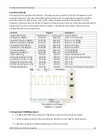
Two inputs on the module are used as the
Triggers
for the High-Speed counters, and two outputs are used as
the
Done
bits. The inputs support a maximum speed of 200 KHz.
The following bits and registers are associated with a High-Speed counter:
Register/ Bit
Description
Configuration
Register
The 16-bit register that controls how the High-Speed counter operates.
Current Count
Register
The 32-bit register that counts the number of times that the Trigger has
transitioned. The specified register is the Least Significant Word (LSW); the next
consecutive register is the Most Significant Word (MSW).
Preset Register
The 32-bit register that defines the number of counts at which the Done bit will be
set (see description of Done Bit below). The specified register is the Least Significant
Word (LSW); the next consecutive register is the Most Significant Word (MSW).
Trigger Bit
The input bit that triggers the count. The counter will increment by one on each bit
transition. The counter can operate on a falling (default) or rising edge.
Enable Bit
The counter will not run unless this bit is set. If this bit is reset while the counter is
running, the current values will be maintained, but the Trigger bit will have no
effect. The Done bit is reset if the Enable bit is reset. If the Current Count value is
greater than or equal to the Preset value, the Done bit is set after the Enable bit is
set again.
Reset Bit
When this bit goes from false to true, the current count will reset to 0 and the Done
bit is reset. The reset occurs even when the Enable bit is reset. The reset is
accomplished by an internal bit or a physical input.
Done Bit
The physical output that turns on when the Current Count is equal to or greater than
the Preset value. The bit remains set until the Reset bit goes true, even if the
counter counts beyond the preset. If the Enable bit is reset, the Done bit will reset. If
the Enable bit is set while the Current Count is equal to or greater than the Preset,
the Done bit is set.
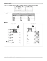
Reference the tables below when configuring each HSC Configuration Register:
Input Mode
Output Mode
Register Value
Normal Input
N/A
0
High Speed,
Single Phase,
Up/Down Counter
Output ON when preset is reached
2
Output ON when counter is enabled,
OFF when preset is reached
258
Quadrature 4X
Output ON when preset is reached
131
Output ON when counter is enabled,
OFF when preset is reached
387
Содержание HMC3-M0808P0401T
Страница 26: ...HMC3 M0808P0401T 26 HMC3000 Series I O Module Guide 26...
Страница 34: ...HMC3 M0808Y0401T 34 HMC3000 Series I O Module Guide 34...
Страница 40: ...HMC3 M1212P0200 40 HMC3000 Series I O Module Guide 40 HSC Single Phase Up Counter HSC Single Phase Down Counter...
Страница 41: ...HMC3 M1212P0200 41 HMC3000 Series I O Module Guide 41 HSC Quadrature...
Страница 47: ...HMC3 M1212Y0200 47 HMC3000 Series I O Module Guide 47 HSC Single Phase Up Counter HSC Single Phase Down Counter...
Страница 48: ...HMC3 M1212Y0200 48 HMC3000 Series I O Module Guide 48 HSC Quadrature...
Страница 55: ...HMC3 M1210P0201 55 HMC3000 Series I O Module Guide 55 HSC Single Phase Down Counter HSC Quadrature...
Страница 56: ...HMC3 M1210P0201 56 HMC3000 Series I O Module Guide 56...
Страница 63: ...HMC3 M1210Y0201 63 HMC3000 Series I O Module Guide 63 HSC Single Phase Down Counter HSC Quadrature...
Страница 67: ...HMC3 M1614Y 67 HMC3000 Series I O Module Guide 67 HSC Single Phase Down Counter HSC Quadrature...
Страница 71: ...HMC3 M1616P 71 HMC3000 Series I O Module Guide 71 HSC Single Phase Down Counter HSC Quadrature...
Страница 72: ...HMC3 M1616P 72 HMC3000 Series I O Module Guide 72...


