Section 4
Maintenance
Part Number 5031216
01/09
4-5
NON-FRONT SERVICEABLE GEAR MOTOR
REMOVAL
These instructions are provided as a guide for the removal of
the gear motor. Depending on the model number of your
dispenser, these instructions may vary slightly.
1. Disconnect power from the electric receptacle.
2. Remove all ice from the ice storage bin of the dispenser.
3. Remove the paddle wheel pin from the paddle wheel/
agitator assembly inside the dispenser bin.
4. Remove the agitator assembly from the dispenser bin by
pushing the agitator to the back of the bin. Angle the front
of the agitator to the side. Pull the agitator forward then
out of the dispenser.
5. Remove the paddle wheel from the dispenser by pulling
the hub of the paddle wheel to the back of the bin and off
the gear motor shaft.
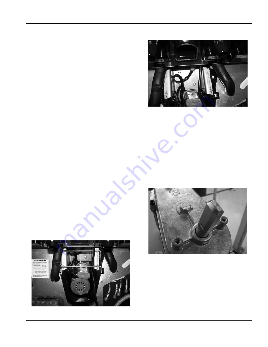
6. Remove the splash panel from the dispenser and expose
the gear motor.
7. Disconnect the electric connector from the gear motor
wire leads.
8. Remove the pin in front of the gear motor.
9. You must be able to remove the gear motor from the
dispenser.
10. To install a replacement gear motor, reverse this
procedure.
FRONT SERVICEABLE GEAR MOTOR REMOVAL
These instructions are provided as a guide for the removal of
the gear motor. Depending on the model number of your
dispenser, these instructions may vary slightly.
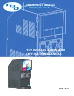
1. Unplug the dispenser.
2. Unplug the motor.
3. Remove motor mount pins.
4. Slide motor towards you.
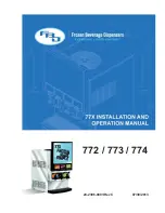
5. Notice alignment of the chamfered edge of drive shaft.
6. New motor must have the same alignment (within
15º degrees).
7. To get correct alignment you can do one of two things:
a. Turn drive shaft with an adjustable wrench, being
careful not to damage the drive shaft.
b. Plug in the unit, plug in the motor and use the ice
dispense switch to move the drive shaft into correct
alignment.
8. If you plugged in the unit to help with alignment of drive
shaft now unplug the unit.
9. Slide motor up into housing, making sure that the tabs fit
on the bracket.
10. Install motor mount pins.
11. Plug in motor.
12. Test unit.
Содержание Multiplex MII-302
Страница 6: ...Part Number 5031216 01 09 4 Table of Contents ...
Страница 22: ...Installation Instructions Section 2 2 14 Part Number 5031216 01 09 THIS PAGE INTENTIONALLY LEFT BLANK ...
Страница 28: ...Operation Section 3 3 6 Part Number 5031216 01 09 THIS PAGE INTENTIONALLY LEFT BLANK ...
Страница 36: ...Maintenance Section 4 4 8 Part Number 5031216 01 09 THIS PAGE INTENTIONALLY LEFT BLANK ...


