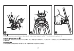
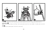
Manfrotto 532 ART Скачать руководство пользователя страница 23

23

POINTES

Le trépied est fourni avec deux pointes métalliques "K" pour un usage en extérieur. Pour utiliser la pointe métallique, retirez le patin "L" en tirant sur la patte en caoutchouc "M". 

MONTAGE D'UNE ROTULE VIDÉO

Ce trépied est conçu pour les rotules livrées avec une boule de 100 mm ou 75 mm. Pour monter une rotule à boule de 75 mm, fixez l'adaptateur "N" (fourni) au trépied à l'aide
des trois vis "M".

REMARQUE

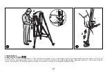
Pour une plus grande stabilité, ramenez le levier "V" (fig. 12) vers le centre du trépied.

K

M

M

N

R

V

L

2

1

10

11

12

10

11

12

Содержание 532 ART

Страница 1: ...542 532 INSTRUCTIONS...

Страница 2: ...raise the tripod with the other hand by pulling the handle C up in one continuous motion until the entire first section is fully extended shown in fig 2 Hold the upper sections figure 3 keeping them p...

Страница 3: ...ripod leveling To adjust the height push down on button E fig 5 With one hand keep the button pressed and tilt the upper part of the tripod until the desired height is reached By pushing the lever F f...

Страница 4: ...essure on the button H fig 7 releases the mechanism allowing spreader adjustment J in five steps To fold the spreader fig 8 lift the center part of the spreader while closing the legs It s possible to...

Страница 5: ...ing down the rubber retainer M MOUNTING A CAMERA HEAD The tripod is designed for 100mm or 75mm ball heads To mount 75mm ball heads attach the adapter N provided to the tripod with the three screws M N...

Страница 6: ...tion fig 14 Keeping the legs tightly closed fig 14 lower the tripod making sure to insert the teeth P into the seats Q fig 15 to lock the legs To keep the legs from sliding push down on the tripod unt...

Страница 7: ...djustment occurs when levers Z align as in fig 18 Please note tightening the screw lowers the corresponding lever loosening raises the corresponding lever 5 Replace protection caps S and V LOWER COLLA...

Страница 8: ...nti e contemporaneamente allungare il treppiede con l altra mano tirando verso l alto la maniglia C con movimento continuo fino ad estendere completamente la prima sezione vedi fig 2 Reggere le sezion...

Страница 9: ...re l altezza premere il pulsante E fig 5 Con una mano tenere premuto il pulsante e inclinare la parte superiore del treppiede fino a raggiungere l altezza desiderata La sezione inferiore delle gambe p...

Страница 10: ...ione sul pulsante H fig 7 sblocca il meccanismo consentendo la regolazione dello stabilizzatore J in cinque passi di apertura Per richiudere lo stabilizzatore fig 8 sollevarne la parte centrale mentre...

Страница 11: ...o il fermo in gomma M MONTAGGIO DELLA TESTA Il treppiede progettato per teste a semisfera da 100mm o 75mm Per montare teste da 75mm attaccare prima al treppiede l adattatore N in dotazione tramite le...

Страница 12: ...mbe saldamente chiuse fig 14 abbassare il treppiede verificando di inserire i denti P nelle sedi Q fig 15 per bloccare le gambe Per prevenire lo scorrimento delle gambe premere sul treppiede fino a se...

Страница 13: ...Z risultano allineate come in fig 18 Da notare il serraggio della vite abbassa la leva corrispondente il suo allentamento la fa sollevare 5 Rimettere in posizione i tappi protettivi S e V MANICOTTO IN...

Страница 14: ...d ziehen Sie das Stativ gleichzeitig mit der anderen Hand am Griff C in einem Zug nach oben bis der gesamte erste Teil voll ausgezogen ist siehe Abb 2 Halten Sie die oberen Teile gem Abb 3 fest achten...

Страница 15: ...des Stativs Zur H heneinstellung dr cken Sie Knopf E Abb 5 Halten Sie den Knopf mit einer Hand gedr ckt und neigen Sie das Oberteil des Stativs bis die gew nschte H he erreicht ist Die Einstellung der...

Страница 16: ...en Druck auf Knopf H Abb 7 hebt die Sperre auf und gestattet die Spreizeneinstellung J in f nf Stufen Zum Einklappen der Mittelspreizen Abb 8 heben sie das Mittelteil w hrend des Schlie ens der Beine...

Страница 17: ...ANSETZEN EINES KAMERAKOPFES Das Stativ ist f r Kugelk pfe 100 mm oder 75 mm konstruiert Zum Aufsetzen eines Kugelkopfes 75 mm montieren Sie den Adapter N im Lieferumfang mit Hilfe der drei Schrauben...

Страница 18: ...vbeine eng geschlossen Abb 14 und dr cken Sie das Stativ nach unten Achten Sie darauf dass die Nasen P in die Halterungen Q Abb 15 eingreifen und die Stativbeine fixieren Um ein ffnen der Beine zu ver...

Страница 19: ...die Hebel Z gem Abb 18 ausgerichtet sind Wichtig Anziehen der Schrauben f hrt zu einer tieferen Hebelstellung L sen zu einer h heren 5 Setzen Sie die Schutzkappen S und V wieder auf UNTERER STATIVKRA...

Страница 20: ...s des deux autres jambes et de l autre tirez le tr pied en tirant sur la poign e C jusqu ce que la premi re section soit compl tement sortie fig 2 Saisissez ensuite les sections sup rieures fig 3 et m...

Страница 21: ...u tr pied appuyez sur le bouton E fig 5 D une main maintenez ce bouton enfonc et inclinez la partie sup rieure du tr pied jusqu atteindre la hauteur souhait e En poussant le levier F fig 6 vers la jam...

Страница 22: ...entretoise J en cinq tapes permettant ainsi de choisir entre 5 positions diff rentes de l entretoise Pour plier l entretoise fig 9 levez sa partie centrale tout en resserrant les jambes du tr pied Vou...

Страница 23: ...la patte en caoutchouc M MONTAGE D UNE ROTULE VID O Ce tr pied est con u pour les rotules livr es avec une boule de 100 mm ou 75 mm Pour monter une rotule boule de 75 mm fixez l adaptateur N fourni au...

Страница 24: ...es fig 14 repliez le tr pied en vous assurant que les pointes P s ins rent dans les anneaux de fixation Q fig 15 afin de bien bloquer les jambes Pour emp cher les jambes de coulisser appuyez sur le tr...

Страница 25: ...s leviers Z sont align s tel qu illustr la figure 18 Remarque lorsque vous serrez la vis le levier correspondant descend et lorsque vous la desserrez il se l ve 5 Remettez les bouchons de protection S...

Страница 26: ...con la otra mano levanten tirando seguidamente hacia arriba la manilla C hasta que toda la primera secci n est completamente tendida fig 2 Sujeten las secci nes superiores fig 3 mantengalas paralelas...

Страница 27: ...tr pode Para ajustar la altura empujen hacia abajo el bot n E fig 5 Con una mano mantengan apretado el bot n e inclinen la secci n superior del tr pode hasta alcanzar la altura deseada Empujando la p...

Страница 28: ...obre el bot n H fig 7 desbloquea el mecanismo permitiendo el ajuste del expansor J a trav s cinco pasos Para plegar el expansor fig 8 levanten la secci n central del expansor mientras cierran las pata...

Страница 29: ...ando abajo el bloqueo de goma M MONTAJE R TULA El tr pode ha sido dise ado para r tulas de bola de 100mm o 75mm Para montar r tulas de bola de 75mm conecten el adaptador N incluido al tr pode con tres...

Страница 30: ...an las patas estrictamente cerradas fig 14 bajen el tr pode asegurandose de introducir los dientes P en los alojamientos Q fig 15 para cerrar las patas Para evitar que las patas deslizen empujen abajo...

Страница 31: ...canza cuando las palancas Z estan alineadas fig 18 Nota apretando el tornillo bajaran la palanca correspondiente mientras aflojandolo la levantaran 5 Ricoloquen las capas de protecci n S y V ABRAZADER...

Страница 32: ...Cod 542 04 09 04 Copyright 2004 Manfrotto Bassano Italy...

Отзывы: