background image

MANDÍK CPV Installation, commissioning, and 

maintenance 


IZU  06/2021 

MANDÍK, a.s., www.mandik.cz


R

48 

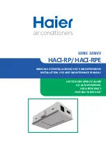
If the unit is equipped with a Climatix controller with a display or POL871 HMI controller, 
the default operating mode is shown on the main screen: 


3)


ADJUSTING THE OPERATING MODE 


The “Protection” / “Economy” / “Comfort” / 

“Schedule” operating mode must be selected to start the unit


Press the button for the “Comfort” operating mode for standard operation.
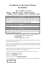


4)


FAN SPEED ADJUSTMENT 
As a default, the unit is started with a defined lower speed limit (35% of output). 
Use the fan button to set higher and the maximum allowed fan speeds: 


DEFAULT OPERATING MODE


“COMFORT” OPERATING 

MODE 

 SUN SYMBOL


BUTTON FOR OPERATING 

MODES


FAN SPEED BUTTON


SHOWING FAN SPEED


LOWEST SPEED - LOWER FAN 

SPEED LIMIT


Содержание CPV

Страница 1: ...MAND K CPV Installation commissioning and maintenance IZU 06 2021 MAND K a s www mandik cz R 1 CPV Compact Air Handling Units INSTALLATION COMMISSIONING MAINTENANCE R...

Страница 2: ...IZU 06 2021 MAND K a s www mandik cz R 2 Contact MAND K a s Dob sk 550 267 24 Hostomice Czech Republic tel 420 311 706 706 fax 420 311 584 810 email mandik mandik cz service department email service...

Страница 3: ...HVAC DUCTWORK 14 6 6 CONDENSATE DRAIN TRAP CONNECTION 14 6 7 HOT COLD WATER COIL CONNECTIONS 15 6 8 ELECTRICAL CONNECTIONS 17 7 ACTIVITIES PRIOR TO COMMISSIONING 19 7 1 GENERAL 19 7 2 INSPECTING THE U...

Страница 4: ...TER COIL COLD WATER COIL 38 9 10 CONDENSER COIL DIRECT EVAPORATOR COIL 38 9 11 PLATE RECUPERATOR 39 9 12 ELECTRIC HEATER 39 ANNEX A QUICK FAN ADJUSTMENT POL871 HMI CONTROLLER 44 ANNEX B QUICK STARTING...

Страница 5: ...roper operation and functionality and to comply with warranty conditions The manufacturer is not liable and the user bears all risks for any damage resulting from improper use This manual is intended...

Страница 6: ...f the unit Declaration of conformity List of fasteners and other materials Drawing documentation for the control system Manual for installation and operation of the control system Other documents onli...

Страница 7: ...Unit type size Order number Production number Construction certificate of the authorised person Filter information Type pressure losses composition Determination of the nameplate for SUPPLY EXHAUST No...

Страница 8: ...vided in the relevant technical specifications The maximum production dimensions specified for the external housing are length x width x height 3880 x 2000 x 2200 mm 3 3 CONNECTION DIMENSIONS A unit m...

Страница 9: ...e unit Commissioning and maintenance instructions are provided in the corresponding sections of this manual The unit must not be operated under these conditions The unit is installed in an environment...

Страница 10: ...for larger units these straps require a spacer from above or additional reinforcement at points where the strap could deform the chamber When transporting by forklift support the chamber along the en...

Страница 11: ...ed appropriately 4 Handling with the unit using steel tubing and straps The tubing must be passed through the round openings in the corner of the frame over the entire length or width of the unit The...

Страница 12: ...aintained to the wiring panel to which the systems are connected Power components circuit breakers contactors switches etc must be clearly labelled in the wiring panel with the number of the equipment...

Страница 13: ...under the frame of the unit at the place of installation The maximum permitted deviation from the horizontal is 0 5 0 3 The unit must be installed at a sufficient height above the floor ground to prov...

Страница 14: ...ements must be properly sealed Specification of the supply return connections on the unit Fig 1 outlets right hand design of CPV unit Fig 2 outlets left hand design of CPV unit 6 6 CONDENSATE DRAIN TR...

Страница 15: ...pressure values is as follows Fig 3 Vacuum trap with ball HL136NGG May be used at vacuum up to 2300 Pa H P 10 P value of the pressure specified in the technical specifications of the unit Pa Fig 4 Tra...

Страница 16: ...guration A capillary freeze protection thermostat is integrated into the unit fully installed and connected to the control system from the factory The mixing loop for heat control if part of delivery...

Страница 17: ...OL822 room unit Touch Panel CO2 sensor piping temperature sensor control loop etc All connection schematics are provided in the design documentation package for the unit MAND K Air Handler Controls Th...

Страница 18: ...connection schematic for models with a hot water coil is provided in Annex D The mains connection schematic for models with an electric heater is provided in Annex E The connection schematic for perip...

Страница 19: ...the previous steps in the installation instructions Prior to commissioning the individual steps below must be completed and recorded in a suitable protocol that is then attached to the operating docum...

Страница 20: ...anness of the chamber interior without foreign bodies and construction Check closing of the unit the door service panels Check the mounting of the roof on outdoor units acc to installation instruction...

Страница 21: ...rator s authorised representative in capital letters in capital letters Record the value only w hen a value needs to be measured SPECIAL OPERATIONS Completion of operation Measured or set value Check...

Страница 22: ...ated air output of the unit Make any changes to controller parameters as follows 1 using the controller s web interface and a laptop computer to simplify the process of connecting the laptop to the co...

Страница 23: ...functions of fire and other quick closing dampers The initial test operation of the unit should be less than 30 minutes The unit and all its sections must then be subjected to a thorough inspection A...

Страница 24: ...ph 8 4 5 Schedule settings see the instructions Detailed instructions for Climatix operation and commissioning available at https mandik cz product line air handling units control system in the Manual...

Страница 25: ...follows Fig 10 Measurement instrument connection Equation for calculating air output h m3 k k factor table above w p measured pressure differential Pa Fan speed is adjusted by changing fan output to c...

Страница 26: ...ng information Identification of the equipment order number serial number position in the project Details as to the person making control changes including their signature and stamp Nominal parameters...

Страница 27: ...andik cz Completion of a record of unit configuration A copy shall be sent by post to MAND K a s or via email to the service department at service mandik cz Handover of the unit to the user Completion...

Страница 28: ...1 DESCRIPTION OF THE UNIT COMPONENTS Fig 11 Components right hand unit design ACCESS TO THE PANEL MAIN SWITCH FILTER RETURN MIXING DAMPER HEAT RECOVERY BY PASS FAN SUPPLY BY PASS DAMPER SHUT OFF DAMPE...

Страница 29: ...ASS EC1 EC2 supply return EC fan M1 supply damper actuator M2 by pass damper actuator M3 return damper actuator M4 mixing damper actuator M5 actuator on the 3 way mixing valve serving the hot cold wat...

Страница 30: ...ces the unit into service is responsible for creating and maintaining the operating log book The operator of the unit then records the individual events SAFETY DURING MAINTENANCE ATTENTION ANY WORK MA...

Страница 31: ...nside Check the air output of the unit when the unit and filters are clean inside Check the unit for excessive vibrations Overall check of the tightness of the doors service and fixed panels on all co...

Страница 32: ...e impeller and the chamber inside 1 3 6 12 4 WATER HEATER 4 01 N repair replaceme nt 4 02 N cleaning 4 03 N repair 4 04 N repair measuring and control system 4 05 N repair 4 06 N repair status of unit...

Страница 33: ...s of the terminal board Check the heating rods for cleanness 6 COLD WATER COIL 6 01 N repair replace 6 02 N clean 6 03 N repair 6 04 N repair clean 6 05 N repair 6 06 N repair 6 07 N clean repair 6 08...

Страница 34: ...geration technician certified for work with refrigerants Method ofservice removal Inspection of the cleanliness and continuity of the condensate drain Inspection of the condition and cleanliness of th...

Страница 35: ...e extended or shortened depending on local operating conditions the nature of the equipment and the pollutants contained in the conveyed air These intervals do not relieve the operator of its obligati...

Страница 36: ...e motor current during maintenance Repair any damaged surfaces Check for proper mounting of the electric motor to the base and all the fasteners on the fan assembly base 9 7 FILTERS Dust captured in f...

Страница 37: ...TS Operable damper blades must be locked to prevent spontaneous or accidental closure Never put your fingers between the blades of an open damper as this is a serious injury hazard Check for dirt and...

Страница 38: ...as been drained from the heat exchanger and the heat exchanger must always be purged subsequently using compressed air For cold water coils also check the condition and operation of all condensate pan...

Страница 39: ...R Operable damper blades must be locked to prevent spontaneous or accidental closure Never put your fingers between the blades of an open damper as this is a serious injury hazard Check the condition...

Страница 40: ...nder operating conditions significantly exceeds the safe contact temperature of 60 C Allow a sufficient amount of time to enable the heating rods to cool before starting any work or activities on the...

Страница 41: ...ccess to the terminal block is provided by removing the 5 0 mm screws from the cover using a hex key The heater terminal block is equipped with a DIN rail for power connection terminals SSR relays for...

Страница 42: ...ed to restart the heaters The operating thermostat is set to 50 C within the air stream as standard while the alarm thermostat is set to a temperature of 80 C in close proximity to the heaters as it i...

Страница 43: ...t The heater may only be switched on once such state is achieved The fan must also run for a minimum of five minutes after the heater has switched off to ensure the heating elements are cooled suffici...

Страница 44: ...e display on the controller and the POL871 HMI controller Buttons on the POL871 HMI controller 1 PASSWORD enter 2222 to access the service level main menu press enter to confirm use the up down arrows...

Страница 45: ...firm Press enter on the Comfort supply return fan row and use the arrows to adjust the fan output value use the arrows to change the value and the press enter to confirm The Comfort value is the upper...

Страница 46: ...cz R 46 ANNEX B QUICK STARTING THE UNIT WEB POL871 HMI CONTROLLER The unit must be put in Economy or Comfort mode to start the unit The default setting from the factor is Off for safety reasons main...

Страница 47: ...When power is connected and the connection is made to the controller the room unit updates its data for a few seconds with the Climatix controller and the P symbol is shown on the display 2 DEFAULT S...

Страница 48: ...otection Economy Comfort Schedule operating mode must be selected to start the unit Press the button for the Comfort operating mode for standard operation 4 FAN SPEED ADJUSTMENT As a default the unit...

Страница 49: ...a s www mandik cz R 49 5 TEMPERATURE SET POINT ADJUSTMENT To change the temperature set point depending on the operating mode use the and buttons to change the temperature set point LOWER TEMPERATURE...

Страница 50: ...MAND K CPV Installation commissioning and maintenance IZU 06 2021 MAND K a s www mandik cz R 50 ANNEX D MAINS CONNECTION HOT WATER HEATING...

Страница 51: ...MAND K CPV Installation commissioning and maintenance IZU 06 2021 MAND K a s www mandik cz R 51 ANNEX E MAINS CONNECTION ELECTRIC HEATING...

Страница 52: ...MAND K CPV Installation commissioning and maintenance IZU 06 2021 MAND K a s www mandik cz R 52 ANNEX F PERIPHERALS CO2 SENSOR POL822 ROOM UNIT PIPING TEMPERATURE SENSOR...

Отзывы: