1
2
3
4
Removing and installing the timing case
112
Removing timing case
D
Removing the starter motor, see page 133
D
Remove crankcase breather
D
Remove the intercooler, see page 91
D
Remove Fuel Service Centre, see page 37
D
Remove sea water pump, see page 60
D
If necessary, remove hydraulic pump
D
If necessary, remove engine bearer
D
Removing the flywheel, see page 77
Fig. 1
Oil and coolant lines, brackets for wiring harnesses
etc. are attached to the timing case, and these
must be removed.
Note:
To facilitate reassembly, memorise or mark
down in a drawing or photo the positions of
the brackets, pipe clamps and spacer
sleeves etc.
Remove the timing case cover.
Fig. 2
Loosen the mounting bolts of the timing case.
Fig. 3
The bottom of the timing case is bolted to the oil
pan! Loosen the mounting bolts of the oil pan.
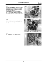
Fig. 4
Danger:
The timing case is heavy!
To facilitate assembly, two bolts on opposite sides
can be replaced by guide pins M12x1.5
À
.
Two long M10
Á
bolts screwed into pocket holes
on the flanging level make it easier to handle the
timing case.
1
1
2
Содержание D 2840 LE 301
Страница 1: ......
Страница 2: ......
Страница 16: ...Notes 14...
Страница 20: ...Engine views 18 Engine views D 2842 LE 301 9 10 11 12 9 8 6 5 4 3 2 1 13 14 15 16 17 18 6 7 8...
Страница 150: ...Notes 148...
Страница 151: ...149 Service Data...
Страница 179: ...177 Special tools...
Страница 180: ...Special tools 178 2 3 4 5 6 7 8 1 6 1 6 2 6 3 9 1 9 2 9 3 9...
Страница 182: ...Special tools 180 10 11 16 14 14 1 12 13 18 18 1 12 1 12 2 15 5 15 4 15 1 15 1 15 2 15 3 15 3 15 6 15 7 15 17...
Страница 184: ...Special tools 182 21 22 25 25 2 24 25 1 26 27 1 27 2 27 20 1 19 2 19 1 20 2 19 20 28 23...
Страница 186: ...Special tools 184 30 29 32 31 33...
Страница 189: ...Special tools 187 2843 Pressing mandrel for cap dia 50 1 mm Pressing mandrel for cap dia 62 1 mm...
Страница 193: ......
Страница 194: ......


