


MAN B&W
7.05
Page of
MAN Diesel
MAN B&W MC/MC-C, ME/ME-C/ME-GI/ME-B engines,
MC/ME Engine selection guides
198 47 35-0.2
Fuel oil filter
The filter can be of the manually cleaned duplex
type or an automatic filter with a manually cleaned
bypass filter.
If a
double filter (duplex) is installed, it should
have sufficient capacity to allow the specified full
amount of oil to flow through each side of the filter
at a given working temperature with a max. 0.
bar pressure drop across the filter (clean filter).
If a
filter with backflushing arrangement is
installed, the following should be noted. The re-
quired oil flow specified in the ‘List of capacities’,
i.e. the delivery rate of the fuel oil supply pump and
the fuel oil circulating pump, should be increased
by the amount of oil used for the backflushing, so
that the fuel oil pressure at the inlet to the main en-
gine can be maintained during cleaning.
In those cases where an
automatically cleaned
filter is installed, it should be noted that in order
to activate the cleaning process, certain makers of
filters require a greater oil pressure at the inlet to
the filter than the pump pressure specified. There-
fore, the pump capacity should be adequate for
this purpose, too.
The fuel oil filter should be based on heavy fuel oil
of: 10 cSt at 80 °C = 700 cSt at 50 °C = 7000 sec
Redwood I/100 °F.
Fuel oil flow .........................see ‘List of capacities’
Working pressure ..........................................10 bar
Test pressure ...................... according to class rule
Absolute fineness .......................................... 50 µm
Working temperature .................. maximum 150 °C
Oil viscosity at working temperature ............15 cSt
Pressure drop at clean filter ........maximum 0. bar
Filter to be cleaned at a pressure
drop of ........................................maximum 0.5 bar
Note:
Absolute fineness corresponds to a nominal fine-
ness of approximately 35 µm at a retaining rate of
90%.
The filter housing shall be fitted with a steam jack-
et for heat tracing.
(
(
(
(
(
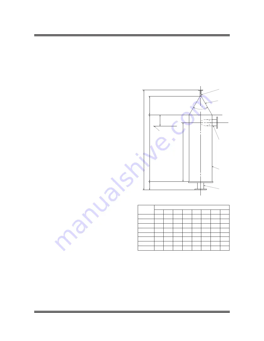
4OPæOFæFUELæOILæ
SERVICEæTANK
6ENTæPIPE
NOMINALæ$
#ONE
)NLETæPIPE
NOMINALæ$
0IPE
NOMINALæ$
/UTLETæPIPE
NOMINALæ$
Fuel oil venting box
The design of the Fuel oil venting box is shown in
Fig. 7.05.02. The size is chosen according to the
maximum flow of the fuel oil circulation pump,
which is listed in section 6.0.
178 38 393.3
Flushing of the fuel oil system
Before starting the engine for the first time, the
system on board has to be flushed in accordance
with MAN Diesel’s recommendations ‘Flushing of
Fuel Oil System’ which is available on request.
Flow m
3
/h
Q (max.)*
Dimensions in mm
D1
D2
D
H1
H2
H
H4
H5
1.
150
2
15
100
600 171. 1,000
550
2.1
150
40
15
100
600 171. 1,000
550
5.0
200
65
15
100
600 171. 1,000
550
8.4
400
80
15
150 1,200 .5 1,800 1,100
11.5
400
90
15
150 1,200 .5 1,800 1,100
19.5
400
125
15
150 1,200 .5 1,800 1,100
29.4
500
150
15
150 1,500 402.4 2,150 1,50
4.0
500
200
15
150 1,500 402.4 2,150 1,50
* The maximum flow of the fuel oil circulation pump
Fig. 07.05.02: Fuel oil venting box
Содержание B&W L35MC6-TII
Страница 4: ......
Страница 10: ......
Страница 18: ......
Страница 19: ...MAN B W MAN Diesel Engine Design 1 ...
Страница 20: ......
Страница 35: ...MAN B W MAN Diesel Engine Layout and Load Diagrams SFOC 2 ...
Страница 36: ......
Страница 52: ......
Страница 64: ......
Страница 65: ...MAN B W MAN Diesel Turbocharger Selection Exhaust Gas By pass 3 ...
Страница 66: ......
Страница 72: ......
Страница 73: ...MAN B W MAN Diesel Electricity Production 4 ...
Страница 74: ......
Страница 85: ...MAN B W Page of 1 MAN Diesel This section is not applicable Waste Heat Recovery Systems WHR 4 05 198 66 47 4 0 ...
Страница 95: ...MAN B W MAN Diesel Installation Aspects 5 ...
Страница 96: ......
Страница 132: ......
Страница 146: ......
Страница 147: ...MAN B W MAN Diesel List of Capacities Pumps Coolers Exhaust Gas 6 ...
Страница 148: ......
Страница 171: ...MAN B W MAN Diesel Fuel 7 ...
Страница 172: ......
Страница 186: ......
Страница 187: ...MAN B W MAN Diesel Lubricating Oil 8 ...
Страница 188: ......
Страница 203: ...MAN B W MAN Diesel Cylinder Lubrication 9 ...
Страница 204: ......
Страница 213: ...MAN B W MAN Diesel Piston Rod Stuffing Box Drain Oil 10 ...
Страница 214: ......
Страница 215: ......
Страница 217: ...MAN B W MAN Diesel Central Cooling Water System 11 ...
Страница 218: ......
Страница 223: ...MAN B W MAN Diesel Seawater Cooling System 12 ...
Страница 224: ......
Страница 234: ......
Страница 235: ...MAN B W MAN Diesel Starting and Control Air 13 ...
Страница 236: ......
Страница 242: ......
Страница 243: ...MAN B W MAN Diesel Scavenge Air 14 ...
Страница 244: ......
Страница 256: ......
Страница 257: ...MAN B W MAN Diesel Exhaust Gas 15 ...
Страница 258: ......
Страница 272: ......
Страница 273: ...MAN B W MAN Diesel Engine Control System 16 ...
Страница 274: ......
Страница 289: ...MAN B W MAN Diesel Vibration Aspects 17 ...
Страница 290: ......
Страница 304: ......
Страница 305: ...MAN B W MAN Diesel Monitoring Systems and Instrumentation 18 ...
Страница 306: ......
Страница 328: ......
Страница 329: ...MAN B W MAN Diesel Dispatch Pattern Testing Spares and Tools 19 ...
Страница 330: ......
Страница 360: ......
Страница 361: ...MAN B W MAN Diesel Project Suppport and Documentation 20 ...
Страница 362: ......
Страница 371: ...MAN B W MAN Diesel Appendix A ...
Страница 372: ......


