


W
iring diagram
P 6 / 6
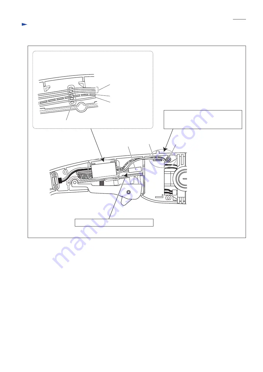
Fig. D-3
[2] Wiring in Handle
Lead wires (white)
of Noise suppressor*
Field lead wire (red)
Field lead wire (white)
Noise suppressor
(if used)
Before setting Switch in place, fix Lead wires
with Lead wire holders under switch as illustrated below.
Lead wire holders
rib
boss
Switch
*If Noise suppressor is used
Route two Field lead wires (red, white)
between the rib and the boss and between
the rib and the inside wall of Handle (L).
Put Noise suppressor in this space if used.


